Nissan Sentra Service Manual: Fender protector
Fender protector
Fender protector : exploded view
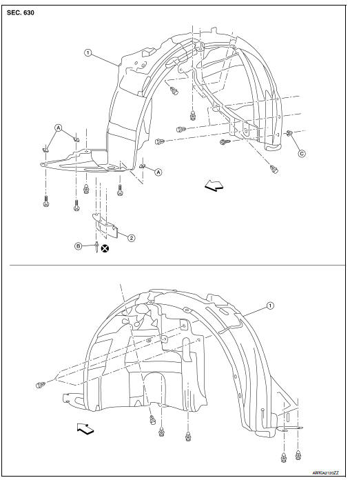
- Front fender protector
- Front wind deflector
- U nut
- Rivet
- Grommet
 Front
Front
Fender protector : removal and installation - front fender protector
REMOVAL
- Remove front wheel and tire. Refer to WT-47, "Adjustment".
- Remove front fender protector screws and clips
- Remove front fender protector from wheel house.
INSTALLATION
Installation is in the reverse order of removal.
Fender protector : exploded view
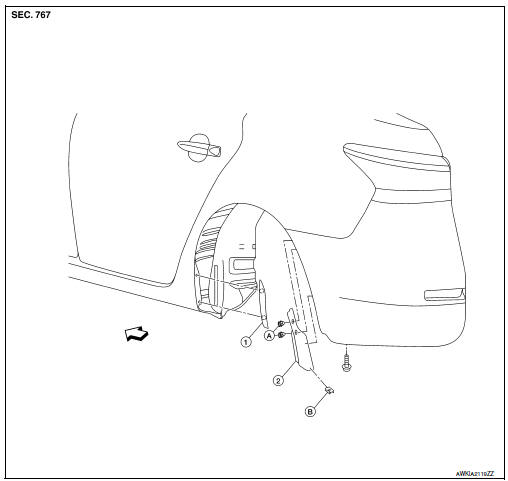
- Rear wheel opening molding
- Rear fender protector
- Clip
- U-clip
 Front
Front
Fender protector : removal and installation - rear fender protector
REMOVAL
- Release the rear wheel opening molding pawls and remove rear wheel opening molding.
- Remove the rear fender protector clips, bolt and the rear fender protector.
INSTALLATION
Installation is in the reverse order of removal.
Rear wind deflector
Rear wind deflector : exploded view
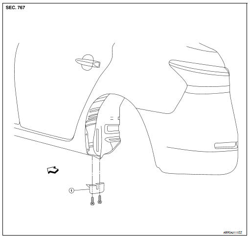
- Rear wind deflector
 Front
Front
Rear wind deflector : removal and installation
REMOVAL
- Remove the rear wind deflector screws and the rear wind deflector.
INSTALLATION
Installation is in the reverse order of removal.
 Cowl top
Exploded view
Cowl top seal
Cowl top grille cap
Cowl top cover
Cowl top extension
Cowl top extension insulator
Clip
EPT seal [t: 3.0 mm (0.12 in)
Cowl top cover cap
EPT seal [t: ...
 Under cover
Front under cover
Front under cover : removal and installation
REMOVAL
Remove front side of front fender protector (LH/RH). Refer to EXT-28,
"FENDER PROTECTOR : Removal
and Installatio ...
Other materials:
Idle speed
Inspection
1.CHECK IDLE SPEED
With CONSULT
Check idle speed in “DATA MONITOR” mode of “ENGINE” using CONSULT.
Specification : EC-486, "Idle Speed"
With GST
Check idle speed with Service $01 of GST.
Specification : EC-486, "Idle Speed"
>> INSPEC ...
Front power window motor
Removal and Installation
REMOVAL
Remove the front door glass regulator (2). Refer to GW-16,
"Removal and Installation".
Remove the bolts (A) and the front power window motor (1).
INSTALLATION
Installation is in the reverse order of removal. ...
Passenger side door mirror defogger
Description
Heats the heating wire with the power supply from the rear window defogger
relay to prevent the door mirror
from fogging up.
Component function check
1.Check door mirror defogger rh
Check that the heating wire of door mirror defogger rh is heated when turning
the rear window de ...
