Nissan Sentra B18 (2020-2025) Service Manual: Engine Coolant
Inspection
Warning:
-
Do not remove the radiator cap or reservoir tank cap when the engine is hot. Serious burns could occur from high-pressure engine coolant escaping from the cooling system.
-
When removing the radiator cap or reservoir tank cap, wrap a thick cloth around the cap and slowly turn it a quarter turn to allow built-up pressure to escape. Then carefully remove the cap by turning it all the way.
CHECKING COOLING SYSTEM HOSES
Check hoses for the following:
-
Improper attachment
-
Leaks
-
Cracks
-
Dents
-
Bulges
-
Internal obstruction
-
Damage
-
Loose connections
-
Chafing
-
Deterioration
CHECKING RESERVOIR LEVEL
-
Check the coolant reservoir tank level when the engine is cool.
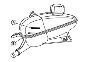
-
Adjust engine coolant level, if necessary, to ensure that the engine coolant level is within the MAX (A) to MIN (B) range.
CAUTION:
Refill Genuine NISSAN Long Life Antifreeze/Coolant (blue) or equivalent in its quality mixed with water (distilled or demineralized). Refer to Fluids and Lubricants.
CHECKING COOLING SYSTEM FOR LEAKS
Warning:
-
Do not remove the radiator cap or reservoir tank cap when the engine is hot. Serious burns could occur from high-pressure engine coolant escaping from the cooling system.
-
When removing the radiator cap or reservoir tank cap, wrap a thick cloth around the cap and slowly turn it a quarter turn to allow built-up pressure to escape. Then carefully remove the cap by turning it all the way.
To check the cooling system for leaks, apply pressure to the cooling system using Tools (A), (B), (C) and (D).
|
Tool number (A) |
: — (NI-51771-5) |
|
Tool number (B) |
: — (NI-51771-9) |
|
Tool number (C) |
: — (NI-51771-1) |
|
Tool number (D) |
: — (NI-51771-4) |
|
Leakage test pressure |
: Refer to Radiator. |
CAUTION:
Higher pressure testing than specified may cause radiator damage.
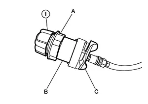
CHECKING RESERVOIR CAP
Warning:
-
Do not remove the radiator cap or reservoir tank cap when the engine is hot. Serious burns could occur from high-pressure engine coolant escaping from the cooling system.
-
When removing the radiator cap or reservoir tank cap, wrap a thick cloth around the cap and slowly turn it a quarter turn to allow built-up pressure to escape. Then carefully remove the cap by turning it all the way.
-
Inspect the reservoir cap.
-
Replace the reservoir cap if there is damage to the O-ring
-
Replace the reservoir cap if deposits of waxy residue or other foreign material are present on inside of reservoir cap.
CAUTION:
Thoroughly wipe out the reservoir filler neck to remove any waxy residue or foreign material.
-
-
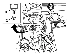
Check the reservoir cap relief pressure
-
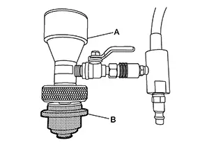
Check reservoir cap relief pressure using Tools.
Tool number (C)
: — (NI-51771–5)
Tool number (B)
: — (NI-51771–9)
Tool number (A)
: — (NI-52558)
Reservoir cap relief pressure
: Refer to Radiator.
-
When connecting the reservoir cap to the Tool, apply water or coolant to the reservoir cap O-ring.
Tool number
: — (NI-52558)
-
Replace the reservoir cap if there is an abnormality in the O-ring or if the open-valve pressure is outside of the standard values.
-
-
CHECKING RADIATOR
Check radiator for mud or clogging. If necessary, clean radiator as follows:
CAUTION:
-
Be careful not to bend or damage the radiator fins.
-
When radiator is cleaned on-Nissan Sentra vehicle, remove surrounding parts in order to access the radiator core. Tape the harness and electrical connectors to prevent water from entering.
Spray water to the back side of the radiator core using a side-to-side motion from the top down.
Stop spraying when debris no longer flows from radiator core.
Blow air into the back side of radiator core using a side-to-side motion from the top down.
-
Use compressed air lower than 490 kPa (5 kg/cm2, 71 psi) and keep a distance of more than 30 cm (11.8 in).
Continue to blow air until no water sprays out.
Check for coolant leaks. Repair as necessary.
Draining
Warning:
-
Do not remove the radiator cap or reservoir tank cap when the engine is hot. Serious burns could occur from high-pressure engine coolant escaping from the cooling system.
-
When removing the radiator cap or reservoir tank cap, wrap a thick cloth around the cap and slowly turn it a quarter turn to allow built-up pressure to escape. Then carefully remove the cap by turning it all the way.
CAUTION:
-
Do not spill coolant on the drive belt while working.
-
Be sure to perform this operation when coolant temperature is cold.
Remove the apron bracket. Refer to Removal and Installation.
Open
radiator drain plug (B) at the bottom of radiator, and then remove
radiator cap. 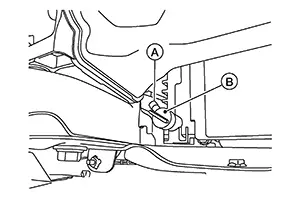
CAUTION:
Perform this step when engine is cold.
Note:
Make sure drain plug hole (A) is aligned with hole in front suspension member.
When
draining all of the engine coolant in the system, complete the
following: Drain
engine coolant from cylinder block by removing water drain plug
(1).
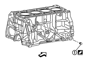
|
|
: Front |
Remove reservoir tank if necessary, and drain engine coolant and clean reservoir tank before installing. Refer to Exploded View.
Check drained engine coolant for contaminants such as rust, corrosion or discoloration. If contaminated, flush the engine cooling system. Refer to Flushing.
Refilling
CAUTION:
-
Do not apply additive agent like anti-leakage sealant. Doing so may cause coolant passage clog.
-
When refilling use Genuine NISSAN Long Life Antifreeze/Coolant (blue) or equivalent in its quality mixed with water (distilled or demineralized). Refer to Fluids and Lubricants.
-
Do not dilute using water.
Install reservoir tank (if necessary). Refer to Exploded View.
Install the
water drain plug (1) (if necessary).
Use Genuine RTV Silicone Sealant or equivalent. Refer to Recommended Chemical Products and Sealants.
|
Water drain plug |
: 9.8 N·m (1.0 kg-m, 87 in-lb) |
|
|
: Front |
Install the radiator drain plug.
-
Replace the drain plug O-ring with a new one.
CAUTION:
Be sure to clean drain plug and install with new O-ring.
|
Radiator drain plug |
: Refer to Exploded View. |
-
If water drain plugs on cylinder block are removed, close and tighten them. Refer to Disassembly and Assembly.
Set the Nissan Sentra vehicle heater controls to the full HOT and heater ON positions. Place the vehicle ignition in the ON position with the engine OFF as necessary to activate the heater mode.
Fill the
cooling system with engine coolant using Tool (A), following the
manufacturer’s instructions included with the tool. 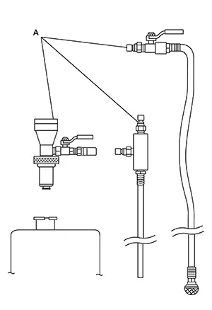
|
Tool number (A) |
: KV991J0070 (NI-45695-A) |
|
Engine Coolant |
: Refer to Fluids and Lubricants. |
CAUTION:
-
Use recommended coolant or equivalent.
-
Do not use any cooling system additives such as radiator sealer. Additives may clog the cooling system and cause damage to the engine, transmission or cooling system.
-
The compressed air supply must be equipped with an air dryer.
When installing Tool (A) to reservoir tank filler neck, make sure to select the correct size expansion plug (B).
Remove the Tool (A) and top off the cooling system with engine coolant as necessary.
Install the reservoir tank cap.
Run the engine until it reaches normal operating temperature.
CAUTION:
Do not allow the engine to exceed normal operating temperature or engine damage may occur.
Stop the engine and allow it to cool.
Check the engine coolant level and adjust if necessary.
Flushing
FLUSHING COOLING SYSTEM
Fill the radiator from the reservoir tank filler neck with clean water and reinstall reservoir tank cap.
Run the engine until it reaches normal operating temperature.
Rev the engine two or three times under no-load.
Stop the engine and wait until it cools down.
Drain the water from the system. Refer to Draining.
Repeat steps 1-5 until clear water begins to drain from the radiator.


Other materials:
G Sensor
Exploded View
G sensor
Bracket
Vehicle front
NВ·m (kg-m, ft-lb)
NВ·m (kg-m, in-lb)
Removal and Installation
WARNING:
Do not leave any objects (screwdrivers, tools, etc.) on the seat during
seat repair. It can lead to personal
injury if the side air bag module should acc ...
Symptom diagnosis
Audio system
Symptom table
Related to audio
Related to hands-free phone
Before performing diagnosis, confirm that the cellular phone being used
by the customer is compatible with
the vehicle.
It is possible that a malfunction is occurring due to a version change
of the p ...
P0507 ISC System
Description
The ECM controls the engine idle speed to a specified level through the fine
adjustment of the air, which is let
into the intake manifold, by operating the electric throttle control actuator.
The operating of the throttle valve is
varied to allow for optimum control of the engine ...
