Nissan Sentra B18 (2020-2025) Service Manual: Electrical Incident Inspection
Work Flow
Work Flow
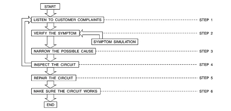
WORK FLOW
|
STEP |
DESCRIPTION |
|
|---|---|---|
|
STEP 1 |
Get detailed information about the conditions and the environment when the incident occurred. The following are key pieces of information required to make a good analysis: |
|
|
WHAT |
Nissan Sentra Vehicle Model, Engine, Transmission/Transaxle and the System (i.e. Radio). |
|
|
WHEN |
Date, Time of Day, Weather Conditions, Frequency. |
|
|
WHERE |
Road Conditions, Altitude and Traffic Situation. |
|
|
HOW |
System Symptoms, Operating Conditions (Other Components Interaction). Service History and if any After Market Accessories have been installed. |
|
|
STEP 2 |
Operate the system, road test if necessary. Verify the parameter of the incident. If the problem cannot be duplicated, refer to ŌĆ£Incident Simulation TestsŌĆØ. |
|
|
STEP 3 |
Get the proper diagnosis materials together including:
Identify where to begin diagnosis based upon your knowledge of the system operation and the customer comments. |
|
|
STEP 4 |
Inspect the system for mechanical binding, loose connectors or wiring damage. Determine which circuits and components are involved and diagnose using the Power Supply Routing and Harness Layouts. |
|
|
STEP 5 |
Repair or replace the incident circuit or component. |
|
|
STEP 6 |
Operate the system in all modes. Verify the system works properly under all conditions. Make sure you have not inadvertently created a new incident during your diagnosis or repair steps. |
|
Control Units and Electrical Parts
Control Units and Electrical Parts
PRECAUTIONS
-
Never reverse polarity of battery terminals.
-
Install only parts specified for a Nissan Sentra vehicle.
-
Before replacing the control unit, check the input and output and functions of the component parts.
-
Do not apply excessive force when disconnecting a connector.
-
Do not apply excessive shock to the control unit by dropping or hitting it.
-
Be careful to prevent condensation in the control unit due to rapid temperature changes and do not let water or rain get on it. If water is found in the control unit, dry it fully and then install it in the Nissan Sentra vehicle.
-
Be careful not to let oil to get on the control unit connector.
-
Avoid cleaning the control unit with volatile oil.
-
Do not disassemble the control unit, and do not remove the upper and lower covers.
-
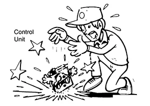
When using a DMM, be careful not to let test probes get close to each other to prevent the power transistor in the control unit from damaging battery voltage because of short circuiting.
-
When checking input and output signals of the control unit, use the specified check adapter.
How to Check Terminal
How to Check Terminal
HARNESS REPAIR KIT
-
When making a harness repair, refer to Connector Repair and Parts Lookup.
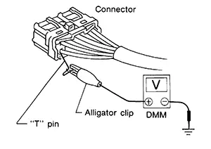
HOW TO PROBE CONNECTORS
-
Connector damage and an intermittent connection can result from improperly probing of the connector during circuit checks.
-
The probe of a digital multimeter (DMM) may not correctly fit the connector cavity. To correctly probe the connector, follow the procedures below using a ŌĆ£TŌĆØ pin. For the best contact grasp the ŌĆ£TŌĆØ pin using an alligator clip.
Probing from Harness Side
Standard type (not waterproof type) connector should be probed from harness side with ŌĆ£TŌĆØ pin.
-
If the connector has a rear cover such as a ECM connector, remove the rear cover before probing the terminal.
-
Do not probe waterproof connector from harness side. Damage to the seal between wire and connector may result.
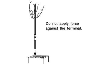
Probing from Terminal Side
FEMALE TERMINAL
-
There is a small notch above each female terminal. Probe each terminal with the ŌĆ£TŌĆØ pin through the notch.
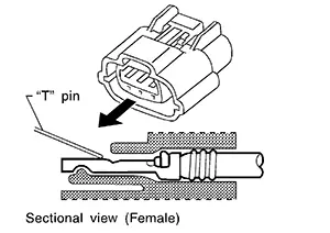
Do not insert any object other than the same type male terminal into female terminal.
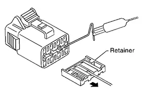
-
Some connectors do not have a notch above each terminal. To probe each terminal, remove the connector retainer to make contact space for probing.
MALE TERMINAL
-
Carefully probe the contact surface of each terminal using a ŌĆ£TŌĆØ pin.
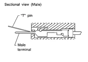
CAUTION:
Dot not bend terminal.
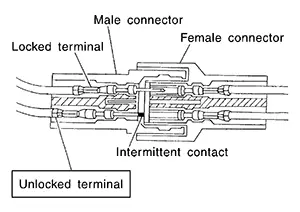
How to Check Enlarged Contact Spring of Terminal
-
An enlarged contact spring of a terminal may create intermittent signals in the circuit.
-
If the intermittent open circuit occurs, follow the procedure below to inspect for open wires and enlarged contact spring of female terminal.
-
Assemble a male terminal and approx. 10 cm (3.9 in) of wire.
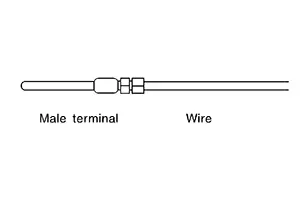 Note:
Note: 
Use a male terminal which matches the female terminal.
-
Disconnect the suspected faulty connector and hold it terminal side up.
-
While holding the wire of the male terminal, try to insert the male terminal into the female terminal.
CAUTION:
Do not force the male terminal into the female terminal with your hands.
-
While moving the connector, check whether the male terminal can be easily inserted or not.
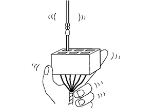
-
If the male terminal can be easily inserted into the female terminal, replace the female terminal.
-
Waterproof Connector Inspection
If water enters the connector, it can short interior circuits. This may lead to intermittent problems.
Check the following items to maintain the original waterproof characteristics.
RUBBER SEAL INSPECTION
-
Most waterproof connectors are provided with a rubber seal between the male and female connectors. If the seal is missing, the waterproof performance may not meet specifications.
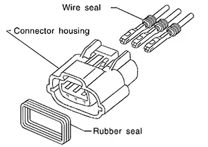
-
The rubber seal may come off when connectors are disconnected. Whenever connectors are reconnected, make sure the rubber seal is properly installed on either side of male or female connector.
WIRE SEAL INSPECTION
-
The wire seal must be installed on the wire insertion area of a waterproof connector. Be sure that the seal is installed properly.
Terminal Lock Inspection
Check for unlocked terminals by pulling wire at the end of connector. An unlocked terminal may create intermittent signals in the circuit.
Circuit Inspection
Circuit Inspection
DESCRIPTION
-
In general, testing electrical circuits is an easy task if it is approached in a logical and organized method. Before beginning it is important to have all available information on the system to be tested. Also, get a thorough understanding of system operation. Then you will be able to use the appropriate equipment and follow the correct test procedure.
-
You may have to simulate Nissan Sentra vehicle vibrations while testing electrical components. Gently shake the wiring harness or electrical component to do this.
|
OPEN |
A circuit is open when there is no continuity through a section of the circuit. |
|
|
SHORT |
There are two types of shorts. |
|
|
When a circuit contacts another circuit and causes the normal resistance to change. |
|
|
When a circuit contacts a ground source and grounds the circuit. |
|
Refer to How to Check Terminal to probe or check terminal.
TESTING FOR ŌĆ£OPENSŌĆØ IN THE CIRCUIT
Before you begin to diagnose and test the system, you should rough sketch a schematic of the system. This will help you to logically walk through the diagnosis process. Drawing the sketch will also reinforce your working knowledge of the system.
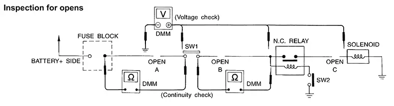
Continuity Check Method
The continuity check is used to find an open in the circuit. The digital multimeter (DMM) set on the resistance function will indicate an open circuit as over limit (no beep tone or no ohms symbol). Make sure to always start with the DMM at the highest resistance level.
To help in understanding the diagnosis of open circuits, please refer to the previous schematic.
-
Disconnect the battery negative cable.
-
Start at one end of the circuit and work your way to the other end. (At the fuse block in this example)
-
Connect one probe of the DMM to the fuse block terminal on the load side.
-
Connect the other probe to the fuse block (power) side of SW1. Little or no resistance will indicate that portion of the circuit has good continuity. If there were an open in the circuit, the DMM would indicate an over limit or infinite resistance condition. (point A)
-
Connect the probes between SW1 and the relay. Little or no resistance will indicate that portion of the circuit has good continuity. If there were an open in the circuit, the DMM would indicate an over limit or infinite resistance condition. (point B)
-
Connect the probes between the relay and the solenoid. Little or no resistance will indicate that portion of the circuit has good continuity. If there were an open in the circuit, the DMM would indicate an over limit or infinite resistance condition. (point C)
Any circuit can be diagnosed using the approach in the previous example.
Voltage Check Method
To help in understanding the diagnosis of open circuits please refer to the previous schematic.
In any powered circuit, an open can be found by methodically checking the system for the presence of voltage. This is done by switching the DMM to the voltage function.
-
Connect one probe of the DMM to a known good ground.
-
Begin probing at one end of the circuit and work your way to the other end.
-
With SW1 open, probe at SW1 to check for voltage.
voltage; open is further down the circuit than SW1.
no voltage; open is between fuse block and SW1 (point A).
-
Close SW1 and probe at relay.
voltage; open is further down the circuit than the relay.
no voltage; open is between SW1 and relay (point B).
-
Close the relay and probe at the solenoid.
voltage; open is further down the circuit than the solenoid.
no voltage; open is between relay and solenoid (point C).
Any powered circuit can be diagnosed using the approach in the previous example.
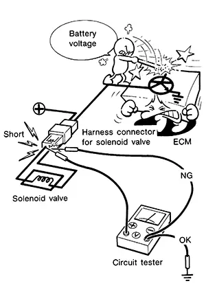
TESTING FOR ŌĆ£SHORTSŌĆØ IN THE CIRCUIT
To simplify the discussion of shorts in the system, please refer to the following schematic.
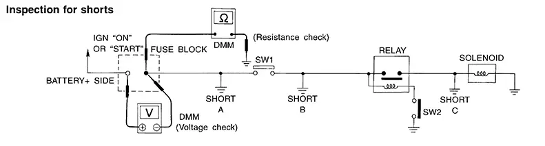
Resistance Check Method
-
Disconnect the battery negative cable and remove the blown fuse.
-
Disconnect all loads (SW1 open, relay disconnected and solenoid disconnected) powered through the fuse.
-
Connect one probe of the DMM to the load side of the fuse terminal. Connect the other probe to a known good ground.
-
With SW1 open, check for continuity.
continuity; short is between fuse terminal and SW1 (point A).
no continuity; short is further down the circuit than SW1.
-
Close SW1 and disconnect the relay. Put probes at the load side of fuse terminal and a known good ground. Then, check for continuity.
continuity; short is between SW1 and the relay (point B).
no continuity; short is further down the circuit than the relay.
-
Close SW1 and jump the relay contacts with jumper wire. Put probes at the load side of fuse terminal and a known good ground. Then, check for continuity.
continuity; short is between relay and solenoid (point C).
no continuity; check solenoid, retrace steps.
Voltage Check Method
-
Remove the blown fuse and disconnect all loads (i.e. SW1 open, relay disconnected and solenoid disconnected) powered through the fuse.
-
Place the ignition to the ON or START position. Verify battery voltage at the battery + side of the fuse terminal (one lead on the battery + terminal side of the fuse block and one lead on a known good ground).
-
With SW1 open and the DMM leads across both fuse terminals, check for voltage.
voltage; short is between fuse block and SW1 (point A).
no voltage; short is further down the circuit than SW1.
-
With SW1 closed, relay and solenoid disconnected and the DMM leads across both fuse terminals, check for voltage.
voltage; short is between SW1 and the relay (point B).
no voltage; short is further down the circuit than the relay.
-
With SW1 closed, relay contacts jumped with fused jumper wire check for voltage.
voltage; short is down the circuit of the relay or between the relay and the disconnected solenoid (point C).
no voltage; retrace steps and check power to fuse block.
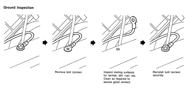
GROUND INSPECTION
-
Ground connections are very important to the proper operation of electrical and electronic circuits. Ground connections are often exposed to moisture, dirt and other corrosive elements. The corrosion (rust) can become an unwanted resistance. This unwanted resistance can change the way a circuit works.
-
Electronically controlled circuits are very sensitive to proper grounding. A loose or corroded ground can drastically affect an electronically controlled circuit. A poor or corroded ground can easily affect the circuit. Even when the ground connection looks clean, there can be a thin film of rust on the surface.
-
When inspecting a ground connection follow these rules:
-
Remove the ground bolt or screw.
-
Inspect all mating surfaces for tarnish, dirt, rust, etc.
-
Clean as required to assure good contact.
-
Reinstall bolt or screw securely.
-
Inspect for ŌĆ£add-onŌĆØ accessories which may be interfering with the ground circuit.
-
If several wires are crimped into one ground eyelet terminal, check for proper crimps. Make sure all of the wires are clean, securely fastened and providing a good ground path. If multiple wires are cased in one eyelet make sure no ground wires have excess wire insulation.
-
-
For detailed ground distribution information, refer to ŌĆ£Ground DistributionŌĆØ in PG section.
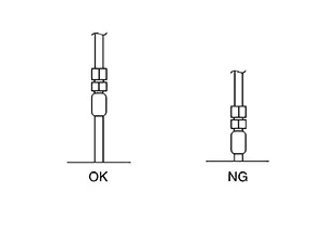
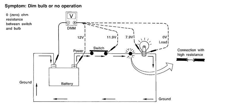
VOLTAGE DROP TESTS
-
Voltage drop tests are often used to find components or circuits which have excessive resistance. A voltage drop in a circuit is caused by a resistance when the circuit is in operation.
-
Check the wire in the illustration. When measuring resistance with DMM, contact by a single strand of wire will give reading of 0 ohms. This would indicate a good circuit. When the circuit operates, this single strand of wire is not able to carry the current. The single strand will have a high resistance to the current. This will be picked up as a slight voltage drop.
-
Unwanted resistance can be caused by many situations as follows:
-
Undersized wiring (single strand example)
-
Corrosion on switch contacts
-
Loose wire connections or splices.
-
-
If repairs are needed always use wire that is of the same or larger gauge.
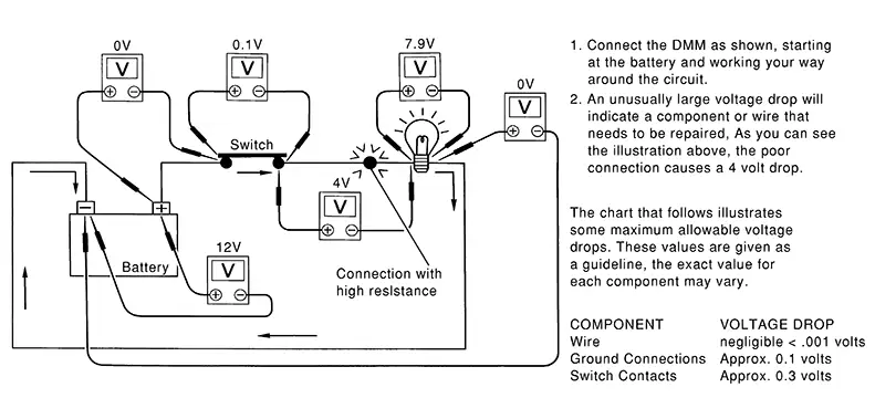
Measuring Voltage Drop ŌĆö Accumulated Method
-
Connect the DMM across the connector or part of the circuit you want to check. The positive lead of the DMM should be closer to power and the negative lead closer to ground.
-
Operate the circuit.
-
The DMM will indicate how many volts are being used to ŌĆ£pushŌĆØ current through that part of the circuit.
Note in the illustration that there is an excessive 4.1 volt drop between the battery and the bulb.
Measuring Voltage Drop ŌĆö Step-by-Step
-
The step-by-step method is most useful for isolating excessive drops in low voltage systems (such as those in ŌĆ£Computer Controlled SystemsŌĆØ).
-
Circuits in the ŌĆ£Computer Controlled SystemŌĆØ operate on very low amperage.
-
The (Computer Controlled) system operations can be adversely affected by any variation in resistance in the system. Such resistance variation may be caused by poor connection, improper installation, improper wire gauge or corrosion.
-
The step by step voltage drop test can identify a component or wire with too much resistance.
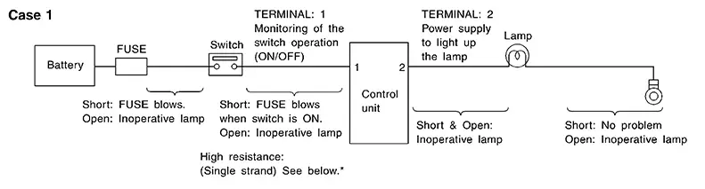
CONTROL UNIT CIRCUIT TEST
System Description
-
When the switch is ON, the control unit lights up the lamp.
CASE 1
|
Terminal No. |
Description |
Condition |
Value (Approx.) |
In case of high resistance such as single strand (V) * |
||
|---|---|---|---|---|---|---|
|
+ |
ŌłÆ |
Signal name |
Input/Output |
|||
|
1 |
Body ground |
Switch |
Input |
Switch ON |
Battery voltage |
Lower than battery voltage Approx. 8 (Example) |
|
Switch OFF |
0 V |
Approx. 0 |
||||
|
2 |
Body ground |
Lamp |
Output |
Switch ON |
Battery voltage |
Approx. 0 (Inoperative lamp) |
|
Switch OFF |
0 V |
Approx. 0 |
||||
-
The voltage value is based on the body ground.
-
*: If high resistance exists in the switch side circuit (caused by a single strand), terminal 1 does not detect battery voltage. Control unit does not detect the switch is ON even if the switch does not turn ON. Therefore, the control unit does not supply power to light up the lamp.
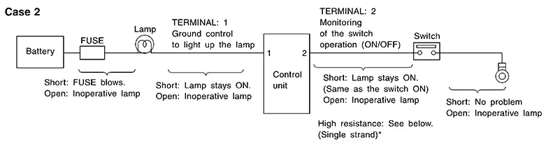
CASE 2
|
Terminal No. |
Description |
Condition |
Value (Approx.) |
In case of high resistance such as single strand (V) * |
||
|---|---|---|---|---|---|---|
|
+ |
ŌłÆ |
Signal name |
Input/Output |
|||
|
1 |
Body ground |
Lamp |
Output |
Switch ON |
0V |
Battery voltage (Inoperative lamp) |
|
Switch OFF |
Battery voltage |
Battery voltage |
||||
|
2 |
Body ground |
Switch |
Input |
Switch ON |
0 V |
Higher than 0 Approx. 4 (Example) |
|
Switch OFF |
5 V |
Approx. 5 |
||||
-
The voltage value is based on the body ground.
-
*: If high resistance exists in the switch side circuit (caused by a single strand), terminal 2 does not detect approx. 0V. Control unit does not detect the switch is ON even if the switch does not turn ON. Therefore, the control unit does not control ground to light up the lamp.
How to Repair Aluminum Wires
How to Repair Aluminum Wires
PRECAUTIONS FOR THE HANDLING OF ALUMINUM WIRES
-
If an aluminum wire is damaged (e.g. broken), never perform the repair method for copper wires (soldering).
-
Never perform electrotap for connecting broken aluminum wires.
-
To secure the wire fixing strength (a force to protect aluminum wire from being disconnected from crimp terminal) and electrical conductivity, always use the dedicated harness repair kit and caulking tool [SST: KV99112600] when repairing broken wires.
HOW TO DISTINGUISH ALUMINUM WIRES
Wiring color: Lavender (Color code: LA)
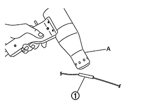
HOW TO REPAIR BROKEN WIRES
-
Insert heat shrinkable tube
 into the target aluminum wire
  beforehand.
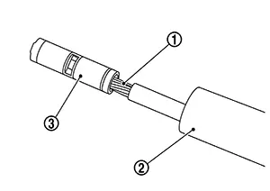
-
Strip wire terminal approximately 10 mm and insert it into crimp terminal
 .
.CAUTION:
Check wire size and use appropriate crimp terminal.
-
Set crimp terminal to the die (tooth) of caulking tool [SST: KV99112600].
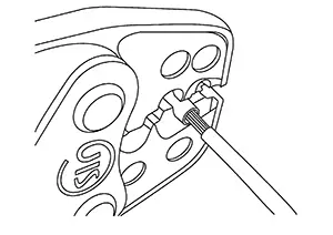
CAUTION:
Use appropriate die (tooth) of caulking tool [SST: KV99112600] according to the crimp terminal size.
-
Apply load until the handle of caulking tool [SST: KV99112600] is released.
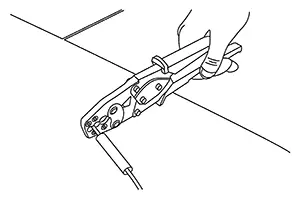 Note:
Note:
The handle of the specified caulking tool [SST: KV99112600] is not opened until crimping is completed.
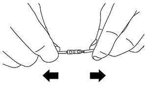
-
After crimping both sides, pull wire at both ends to check that they are not disconnected from crimp terminals.
-
Cover the crimp terminal with heat shrinkable tube
and heat the tube with industrial dryer  .
.
-
After heating heat shrinkable tube
, check that adhesive is squeezed out from both ends of tube to the
entire perimeter.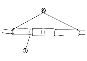
-
Wind insulating tape
around heat shrinkable tube for the purpose of
waterproof and anticorrosion.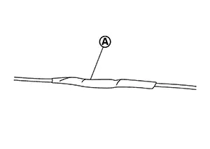
HOW TO EXTEND WIRES
When repairing a broken aluminum wire, it can be
extended by connecting aluminum wire
with copper wire
by using crimp terminal .

Other materials:
Removal and Installation. 8ch Can Gateway
8ch Can Gateway
Removal and Installation
Removal and Installation
CAUTION:
If replacing 8CH CAN gateway, Perform "ADDITIONAL
SERVICE WHEN REPLACING 8CH CAN GATEWAY". Refer to Work Procedure.
REMOVAL
Remove
instrument panel assembly. Refer to Removal and Installation ...
Fuel Tank Temperature Sensor
Component Inspection
Component Inspection
CHECK FUEL TANK TEMPERATURE (FTT)
SENSOR
Turn ignition switch OFF.
Disconnect fuel level sensor unit and
fuel pump harness connector.
Remov ...
Hazard Switch
Component Inspection
Component Inspection
CHECK HAZARD SWITCH
Ignition switch OFF.
Disconnect hazard switch connector.
Check continuity between hazar ...