Nissan Sentra B18 (2020-2025) Service Manual: Ecu Diagnosis Information
Av Control Unit
Values on the Diagnosis Tool
Values on the Diagnosis Tool
Note:
The following table includes information (items) inapplicable to this Nissan Sentra vehicle. For information (items) applicable to this vehicle, refer to CONSULT display items.
|
Monitor Item |
Condition |
Value/Status |
|---|---|---|
|
Sunload sensor |
— |
Off |
|
— |
On |
|
|
Parking brake |
Parking brake not applied. |
Off |
|
Parking brake applied. |
On |
|
|
IGN SIG |
Ignition switch OFF. |
Off |
|
Ignition switch ON. |
On |
|
|
Auto ACC |
Auto accessory mode OFF. |
Off |
|
Auto accessory mode ON. |
On |
|
|
ACC |
Accessory mode OFF. |
Off |
|
Accessory mode ON. |
On |
|
|
Aux IN 1 |
Accessory not connected to aux in jack. |
Off |
|
Accessory connected to aux in jack. |
On |
|
|
Aux IN 2 |
Accessory not connected to USB. |
Off |
|
Accessory connected to USB. |
On |
|
|
TCU mute signal |
TCU not sending mute signal. |
Off |
|
TCU sending mute signal. |
On |
|
|
REV SIG |
Selector lever in any position other than R. |
Off |
|
Selector lever in R position. |
On |
|
|
ILLUM SIG |
Illumination signal not received. |
Off |
|
Illumination signal received. |
On |
|
|
Illumination Control |
Illumination control signal not received. |
Off |
|
Illumination control signal received. |
On |
Reference Value
Reference Value
TERMINAL LAYOUT
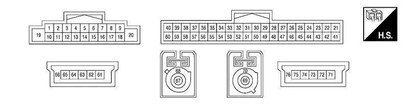
PHYSICAL VALUES
|
Terminal (Wire color) |
Description |
Condition |
Reference value (Approx.) |
|||
|---|---|---|---|---|---|---|
|
+ |
– |
Signal name |
Input/Output |
Ignition switch |
Operation |
|
|
1 (Y) |
Ground |
Bose speaker amp. ON signal |
Output |
ON |
— |
Battery voltage |
|
2 (BR) |
3 (SB) |
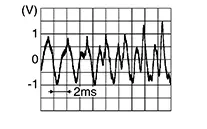
Pre-amp sound signal front LH |
Output |
ON |
Sound output |
 |
|
4 (LG) |
5 (P) |
Pre-amp sound signal rear LH |
Output |
ON |
Sound output |
|
|
10 (LA/B) |
— |
Pre-amp sound signal shield |
— |
— |
— |
— |
|
11 (B) |
12 (W) |
Pre-amp sound signal front RH |
Output |
ON |
Sound output |
|
|
13 (G) |
14 (R) |
Pre-amp sound signal rear RH |
Output |
ON |
Sound output |
|
|
19 (P) |
Ground |
Battery power supply |
Input |
OFF |
— |
Battery voltage |
|
20 (B) |
Ground |
Ground |
— |
ON |
— |
0 V |
|
21 (V)1 (B)2 |
42 (Shield)1 (LA/B)2 |
Microphone signal |
Input |
ON |
While speaking into microphone. |
|
|
22 (LG) |
Ground |
MIC VCC |
Output |
ON |
— |
5 V |
|
27 (L) |
Ground |
AUX jack audio signal RH |
Input |
ON |
Received audio signal (AUX input) |
|
|
28 (Y) |
Ground |
AUX ground |
— |
ON |
— |
0 V |
|
292 (W) |
492 (B) |
Telematics microphone signal |
Input |
ON |
While speaking into microphone. |
|
|
302 (Shield) |
— |
Telematics microphone signal shield |
— |
— |
— |
— |
|
32 (W) |
Ground |
Camera ground |
— |
ON |
— |
0 V |
|
33 (R) |
Ground |
Camera power supply |
Output |
ON |
Camera image displayed |
6.0 V |
|
Except for above |
0 V |
|||||
|
38 (LA/SB) |
— |
AV communication high |
Input/Output |
— |
— |
— |
|
39 (LA/SB) |
— |
AV communication high |
Input/Output |
— |
— |
— |
|
40 (LA/SB) |
— |
CAN-High |
Input/Output |
— |
— |
— |
|
47 (G) |
Ground |
AUX jack audio signal LH |
Input |
ON |
Received audio signal (AUX input) |
|
|
48 (Shield) |
— |
AUX signal shield |
— |
— |
— |
— |
|
50 (Y) |
— |
HF/VR mode change |
— |
— |
— |
— |
|
52 (B) |
53 (Shield) |
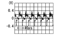
Camera image signal |
Input |
ON |
Camera image displayed |
 |
|
58 (LA/LG) |
— |
AV communication low |
Input/Output |
— |
— |
— |
|
59 (LA/LG) |
— |
AV communication low |
Input/Output |
— |
— |
— |
|
60 (LA/V) |
— |
CAN-Low |
Input/Output |
— |
— |
— |
|
61 (Y) |
— |
USB ground |
— |
— |
— |
— |
|
63 (L) |
— |
USB D+ signal |
— |
— |
— |
— |
|
64 (G) |
— |
USB D− signal |
— |
— |
— |
— |
|
65 (R) |
— |
V BUS signal |
— |
— |
— |
— |
|
66 (Shield) |
— |
USB shield |
— |
— |
— |
— |
|
67 (B) |
Ground |
AM/FM antenna signal |
Input |
ON |
AV control unit ON, FM-AM selected. |
5.0 V |
|
68 (Shield) |
— |
AM/FM antenna shield |
— |
— |
— |
— |
|
69 (B) |
Ground |
Satellite antenna signal |
Input |
ON |
AV control unit ON, XM selected. |
5.0 V |
|
70 (Shield) |
— |
Satellite antenna shield |
— |
— |
— |
— |
|
712 (B) |
— |
USB ground |
— |
— |
— |
— |
|
732 (G) |
— |
USB D+ signal |
— |
— |
— |
— |
|
742 (W) |
— |
USB D− signal |
— |
— |
— |
— |
|
752 (R) |
— |
V BUS signal |
— |
— |
— |
— |
|
762 (Shield) |
— |
USB shield |
— |
— |
— |
— |
1: Without Telematics System
2: With Telematics System
Fail Safe
Fail Safe
|
DTC |
AV control unit operation in fail-safe mode |
|---|---|
|
B1305-04 |
AV control unit internal error |
|
B1309-11 |
No sound from Bose speaker amp. |
|
B1309-12 |
|
|
B1317-11 |
No satellite radio reception |
|
B1317-13 |
|
|
B1328-11 |
Microphone is inoperative |
|
B1328-12 |
|
|
B1328-13 |
|
|
B132A-01 |
USB is inoperative |
|
B132A-13 |
|
|
B132A-49 |
|
|
B132C-01 |
Telematics system inoperative |
|
B132C-13 |
|
|
B132C-49 |
|
|
B133A-8F |
Camera image is inoperative |
|
B1341-16 |
Battery protection shuts AV control unit down 60 seconds after low voltage condition |
|
B1341-17 |
|
|
B1341-49 |
AV control unit internal failure |
|
B1341-55 |
AV control unit configuration error |
|
B1341-98 |
AV control unit shuts down after 5 seconds |
|
B1342-62 |
Audio and visual system features are unavailable |
|
B1343-41 |
AV control unit ROM error |
|
B1344-41 |
AV control unit EEPROM error |
|
B1345-49 |
AV control unit GYRO error |
|
B1347-49 |
Bluetooth® is inoperative |
|
B1351-4B |
AV control unit shuts down and cannot restart for more than 5 minutes |
|
B1356-49 |
AV control unit DSP error |
|
B135E-49 |
AV control unit fan error |
|
B1360-02 |
Steering switch is inoperative |
|
B1380-49 |
Wi-fi function is inoperative |
|
B1383-01 |
Predictive course line is not displayed |
|
B13CF-73 |
AV control unit buttons error |
|
B13D9-8F |
USB devices connected to front auxiliary input jacks are inoperative |
|
B13E5-8F |
Telematics system inoperative |
|
U0079-00 |
CAN communication does not function |
|
U1000-01 |
Function of CAN communication signals received by AV control unit are inoperative |
|
U1300-01 |
AV communication is inoperative |
Dtc Inspection Priority Chart
DTC Inspection Priority Chart
If multiple DTCs are detected simultaneously, check them one by one depending on the following DTC inspection priority chart:
|
Priority |
Detected items (DTC) |
|---|---|
|
1 |
|
|
2 |
|
|
3 |
|
Dtc Index
DTC Index
|
CONSULT Display |
Reference Page |
|---|---|
|
B1305-04: Control unit internal error |
DTC Description |
|
B1309-11: System ON |
DTC Description |
|
B1309-12: System ON |
|
|
B1317-11: XM antenna connection |
DTC Description |
|
B1317-13: XM antenna connection |
|
|
B1328-11: External microphone 1 |
DTC Description |
|
B1328-12: External microphone 1 |
|
|
B1328-13: External microphone 1 |
|
|
B132A-01: External USB |
DTC Description |
|
B132A-13: External USB |
|
|
B132A-49: External USB |
|
|
B132C-01: TCU Connection |
DTC Description |
|
B132C-13: TCU Connection |
|
|
B132C-49: TCU Connection |
|
|
B133A-8F: AVM connection |
DTC Description |
|
B1341-16: Head unit |
DTC Description |
|
B1341-17: Head unit |
|
|
B1341-49: Head unit |
|
|
B1341-55: Head unit |
|
|
B1341-98: Head unit |
|
|
B1342-62: Locked system |
DTC Description |
|
B1343-41: ECU Rom |
DTC Description |
|
B1344-41: ECU EEPROM |
DTC Description |
|
B1345-49: ECU Gyro |
DTC Description |
|
B1347-49: ECU Bluetooth module |
DTC Description |
|
B1351-4B: ECU Amplifier |
DTC Description |
|
B1356-49: ECU DSP |
DTC Description |
|
B135E-49: ECU Fan |
DTC Description |
|
B1360-02: Combination meter |
DTC Description |
|
B1380-49: ECU Wifi module |
DTC Description |
|
B1383-01: Incomp steering angle sensor adjust |
DTC Description |
|
B13CF-73: Buttons |
DTC Description |
|
B13D9-8F: USB communication error |
DTC Description |
|
B13E5-8F: TCU connection |
DTC Description |
|
U0079-00: Control module communication Bus G Off |
DTC Description |
|
U1000-01: CAN COMM CIRCUIT |
DTC Description |
|
U1300-01: AV communication circuit |
DTC Description |
Bose Speaker Amp
Values on the Diagnosis Tool
Values On The Diagnosis Tool
Note:
The following table includes information (items) inapplicable to this Nissan Sentra vehicle. For information (items) applicable to this vehicle, refer to CONSULT display items.
|
Monitor Item |
Condition |
Value/Status |
|---|---|---|
|
CONFIGURATION (AUDIO) |
Audio configuration type |
Numerical |
|
ANC OPERATING CONDITION |
Active noise cancellation not applied. |
Off |
|
Active noise cancellation applied. |
On |
|
|
ASC OPERATING CONDITION |
Active sound enhancement not applied. |
Off |
|
Active sound enhancement applied. |
On |
|
|
ENGINE SPEED |
Engine RPM status from ECM via CAN communication. |
rpm |
|
Nissan Sentra Vehicle speed |
Vehicle speed status from combination meter via CAN communication. |
km/h/mph |
|
DOOR STATUS |
Door closed status from BCM via CAN communication. |
Close |
|
Door open status from BCM via CAN communication. |
Open |
Reference Value
Reference Value
TERMINAL LAYOUT
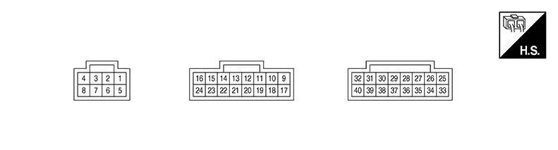
PHYSICAL VALUES
|
Terminal (Wire color) |
Description |
Condition |
Reference value (Approx.) |
|||
|---|---|---|---|---|---|---|
|
+ |
– |
Signal name |
Input/Output |
Ignition switch |
Operation |
|
|
1 (SB) |
5 (B) |
Battery power supply |
Input |
OFF |
— |
Battery voltage |
|
2 (P) |
6 (BR) |
Sound signal front door speaker LH |
Output |
ON |
Sound output |
|
|
3 (W) |
7 (B) |
Sound signal rear speaker LH |
Output |
ON |
Sound output |
|
|
5 (B) |
— |
Ground |
— |
ON |
— |
0 V |
|
8 (G) |
4 (R) |
Sound signal front door speaker RH |
Input |
ON |
Sound output |
|
|
9 (G) |
17 (BR) |
Sound signal rear speaker RH |
Output |
ON |
Sound output |
|
|
11 (G) |
10 (W) |
Sound signal rear door speaker LH |
Output |
ON |
Sound output |
|
|
12 (BG) |
13 (P) |
Sound signal rear door speaker RH |
Output |
ON |
Sound output |
|
|
15 (Y) |
14 (W) |
Sound signal front tweeter RH |
Output |
ON |
Sound output |
|
|
16 (V) |
24 (SB) |
Sound signal front tweeter LH |
Output |
ON |
Sound output |
|
|
18 (GR) |
Ground |
Amp. ON signal |
Output |
ON |
— |
Battery voltage |
|
19 (B) |
5 (B) |
Ignition power supply |
Input |
ON |
— |
Battery voltage |
|
22 (L) |
— |
CAN-High |
Input/Output |
— |
— |
— |
|
23 (R) |
— |
CAN-Low |
Input/Output |
— |
— |
— |
|
29 (LG) |
37 (SB) |
Sound signal rear RH |
Input |
ON |
Sound output |
|
|
30 (B) |
38 (W) |
Sound signal rear LH |
Input |
ON |
Sound output |
|
|
31 (BR) |
39 (P) |
Sound signal front RH |
Input |
ON |
Sound output |
|
|
32 (G) |
40 (R) |
Sound signal front LH |
Input |
ON |
Sound output |
|
Dtc Index
DTC Index
|
CONSULT Display |
Reference Page |
|---|---|
|
B1F05–29: CAN sig error/diag |
DTC Description |
|
U1000–01: CAN COMM CIRCUIT |
DTC Description |
|
U1010–49: CONTROL UNIT(CAN) |
DTC Description |
|
U1231–98: Amplifier temperature |
DTC Description |
|
U1600-11: Front left door speaker out |
DTC Description |
|
U1600-12: Front left door speaker out |
|
|
U1600-13: Front left door speaker out |
|
|
U1600-1A: Front left door speaker out |
|
|
U1608-11: Front right door speaker out |
DTC Description |
|
U1608-12: Front right door speaker out |
|
|
U1608-13: Front right door speaker out |
|
|
U1608-1A: Front right door speaker out |
|
|
U164B-11: Front pillar left tweeter out |
DTC Description |
|
U164B-12: Front pillar left tweeter out |
|
|
U164B-13: Front pillar left tweeter out |
|
|
U164B-1A: Front pillar left tweeter out |
|
|
U1653-11: Front pillar right tweeter out |
DTC Description |
|
U1653-12: Front pillar right tweeter out |
|
|
U1653-13: Front pillar right tweeter out |
|
|
U1653-1A: Front pillar right tweeter out |
|
|
U1709-11: Rear left door woofer out |
DTC Description |
|
U1709-12: Rear left door woofer out |
|
|
U1709-13: Rear left door woofer out |
|
|
U1709-1A: Rear left door woofer out |
|
|
U1711-11: Rear right door woofer out |
DTC Description |
|
U1711-12: Rear right door woofer out |
|
|
U1711-13: Rear right door woofer out |
|
|
U1711-1A: Rear right door woofer out |
|
|
U1721-11: Rear parcel shelf left woofer out |
DTC Description |
|
U1721-12: Rear parcel shelf left woofer out |
|
|
U1721-13: Rear parcel shelf left woofer out |
|
|
U1721-1A: Rear parcel shelf left woofer out |
|
|
U1729-11: Rear parcel shelf right woofer out |
DTC Description |
|
U1729-12: Rear parcel shelf right woofer out |
|
|
U1729-13: Rear parcel shelf right woofer out |
|
|
U1729-1A: Rear parcel shelf right woofer out |
Other materials:
Tire Pressure Monitoring System (TPMS)
Each tire on the Nissan Sentra, including the spare tire if equipped, should
be inspected at least once a month when the tires are cold and inflated to the pressure
recommended by the vehicle manufacturer. This information is shown on the vehicle
placard or the tire inflation pressure label. I ...
Front Regulator
Exploded View
Exploded View
1.
Door glass rubber
run
2.
Front door glass
front run
...
Ecv (electrical Control Valve)
Diagnosis Procedure
Diagnosis Procedure
CHECK ECV POWER SUPPLY
Ignition switch OFF.
Disconnect A/C compressor connector.
Ignition switch ON.
...