Nissan Sentra Service Manual: Ducts and grilles
Exploded View
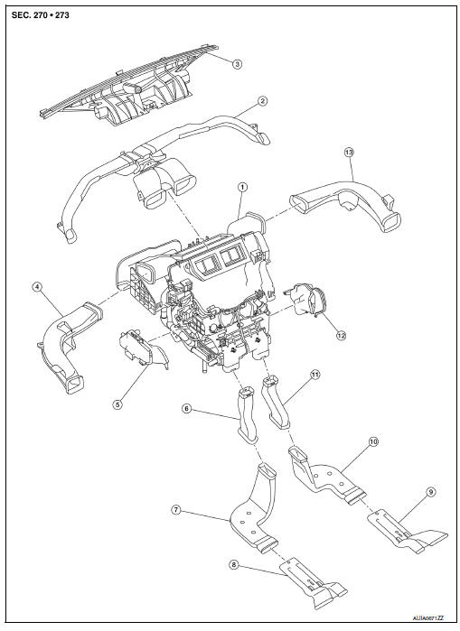
- Heating and cooling unit assembly
- Center ventilator duct
- Defroster duct
- Side ventilator duct (LH)
- Front floor duct (LH)
- Rear floor connecting duct (LH)
- Rear floor duct (LH)
- Rear floor duct nozzle (LH)
- Rear floor duct nozzle (RH)
- Rear floor duct (RH)
- Rear floor connecting duct (LH)
- Front floor duct (RH)
- Side ventilator duct (RH)
Defroster nozzle
DEFROSTER NOZZLE : Removal and Installation
REMOVAL
- Remove the side defroster ducts (LH/RH). Refer to VTL-7, "SIDE VENTILATOR DUCT : Removal and Installation".
- Remove the defroster nozzle screws.
- Remove the defroster nozzle.
INSTALLATION
Installation is in the reverse order of removal.
Center ventilator duct
CENTER VENTILATOR DUCT : Removal and Installation
REMOVAL
- Remove the instrument panel assembly. Refer to IP-14, "Removal and Installation".
- Remove the center ventilator duct screws.
- Remove the center ventilator duct.
INSTALLATION
Installation is in the reverse order of removal.
Side ventilator duct
SIDE VENTILATOR DUCT : Removal and Installation
REMOVAL
- Remove the instrument panel assembly. Refer to IP-14, "Removal and Installation".
- Remove the side ventilator duct screws.
- Release the side ventilator duct from the defroster duct and remove.
INSTALLATION
Installation is in the reverse order of removal.
Rear floor duct
REAR FLOOR DUCT : Removal and Installation - Rear Floor Connecting Duct
REMOVAL
- Remove the center console side finisher. Refer to IP-17, "Exploded View".
- Remove the rear floor connecting duct (LH/RH).
INSTALLATION
Installation is in the reverse order of removal.
REAR FLOOR DUCT : Removal and Installation - Rear Floor Duct
REMOVAL
- Remove the front floor trim. Refer to INT-35, "Removal and Installation".
- Remove the floor insulator
- Release the rear floor duct nozzle from the rear floor duct and remove.
INSTALLATION
Installation is in the reverse order of removal.
REAR FLOOR DUCT : Removal and Installation - Rear Floor Duct Nozzle
REMOVAL
- Remove the rear floor duct. Refer to VTL-8, "REAR FLOOR DUCT : Removal and Installation - Rear Floor Duct Nozzle".
- Remove the rear floor duct nozzle (LH/RH).
INSTALLATION
Installation is in the reverse order of removal.
Exploded View
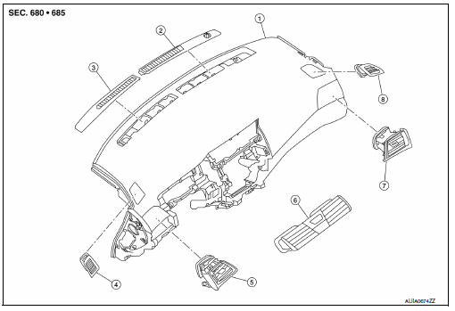
- Instrument panel assembly
- Defroster grille (RH)
- Defroster grille (LH)
- Side defroster grille (LH)
- Side ventilator grille (LH)
- Center ventilator grille
- Side ventilator grille (RH)
- Side defroster grille (RH)
Defroster grille
DEFROSTER GRILLE : Removal and Installation
REMOVAL
- Release the defroster grille pawls using a suitable tool.
- Remove the defroster grille (LH/RH).
INSTALLATION
Installation is in the reverse order of removal.
Center ventilator grille
CENTER VENTILATOR GRILLE : Removal and Installation
REMOVAL
- Remove cluster lid C. Refer to IP-20, "Removal and Installation - Cluster Lid C".
- Release the center ventilator grille pawls using a suitable tool.
- Remove the center ventilator grille (LH/RH).
INSTALLATION
Installation is in the reverse order of removal.
Side ventilator grille
SIDE VENTILATOR GRILLE : Removal and Installation
REMOVAL
- Remove the instrument side finisher. Refer to IP-14, "Exploded View".
- Remove the side ventilator grille screw (A).

- Remove the side ventilator grille (LH/RH).
INSTALLATION
Installation is in the reverse order of removal.
Side defroster grille
SIDE DEFROSTER GRILLE : Removal and Installation
REMOVAL
- Remove the center ventilator duct. Refer to VTL-7, "CENTER VENTILATOR DUCT : Removal and Installation".
- Release the side defroster grille pawl using a suitable tool.
- Remove the side defroster grille (LH/RH).
INSTALLATION
Installation is in the reverse order of removal.

 Blower motor
Exploded View
Heating and cooling unit assembly
Blower motor
Front
Removal and Installation
Remove the glove box assembly. Refer to IP-22, "Removal and
Installation".
...
Other materials:
Precaution for Supplemental Restraint System (SRS) "AIR BAG" and "SEAT BELT
PRE-TENSIONER"
The Supplemental Restraint System such as “AIR BAG” and “SEAT BELT PRE-TENSIONER”,
used along
with a front seat belt, helps to reduce the risk or severity of injury to the
driver and front passenger for certain
types of collision. Information necessary to service the system ...
Checking bulbs
With all doors closed, apply the parking brake
and place the ignition switch in the ON position
without starting the engine. The following lights
will come on:
If equipped, the following lights come on briefly
and then go off:
If any light fails to come on, it may indicate
an open circuit ...
C1130 Engine signal
DTC Logic
DTC DETECTION LOGIC
DTC
Display Item
Malfunction detected condition
Possible causes
C1130
ENGINE SIGNAL 1
When a malfunction is detected in ECM system.
ECM
ABS actuator and electric unit
(control unit)
CAN communication line
...
