Nissan Sentra Service Manual: DTC/circuit diagnosis
P1610 LOCK MODE
Description
ECM forcibly switches to the mode that inhibits engine start, when engine start operation is performed 5 times or more while communication between ECM and BCM is not normal.
DTC Logic
DTC DETECTION LOGIC
NOTE:
If DTC P1610 is displayed with other DTC (for BCM or ENGINE), first perform the trouble diagnosis for other DTC.

DTC CONFIRMATION PROCEDURE
1.PERFORM DTC CONFIRMATION PROCEDURE
- Turn ignition switch ON.
- Check DTC in “Self Diagnostic Result” mode of ENGINE using CONSULT.
Is DTC detected? YES >> Go to SEC-63, "Diagnosis Procedure".
NO >> Inspection End.
Diagnosis Procedure
1.CHECK ENGINE START FUNCTION
- Check that DTC except for DTC P1610 is not detected.
If detected, erase the DTC after fixing.
- Turn ignition switch OFF.
- Depress brake pedal and contact the registered Intelligent Key backside to push-button ignition switch, then wait 5 seconds.
- Turn ignition switch ON.
- Turn ignition switch OFF and wait 5 seconds.
- Repeat steps 3 and 5 twice (a total of 3 times).
- Check that engine can start.
>> Inspection End.
P1611 ID DISCORD, IMMU-ECM
DTC Logic
DTC DETECTION LOGIC
| DTC No. | Trouble diagnosis name | DTC detecting condition | Possible cause |
| P1611 | ID DISCORD, IMMU-ECM | The ID verification results between BCM and ECM are invalid. |
|
DTC CONFIRMATION PROCEDURE
1.PERFORM DTC CONFIRMATION PROCEDURE
- Turn ignition switch ON.
- Check DTC in Self Diagnostic Result mode of ENGINE using CONSULT.
Is DTC detected? YES >> Go to SEC-64, "Diagnosis Procedure".
NO >> Inspection End.
Diagnosis Procedure
1.PERFORM INITIALIZATION
Perform initialization of BCM and registration of all Intelligent Keys using CONSULT.
Can the system be initialized and can the engine be started with registered Intelligent Key? YES >> Inspection End.
NO >> GO TO 2.
2.CHECK SELF DIAGNOSTIC RESULT
- Select Self Diagnostic Result mode of ENGINE using CONSULT.
- Erase DTC.
- Perform DTC CONFIRMATION PROCEDURE for DTC P1611. Refer to SEC-64, "DTC Logic".
Is DTC detected? YES >> GO TO 3.
NO >> Inspection End
3.REPLACE BCM
- Replace BCM. Refer to BCS-73, "Removal and Installation".
- Perform initialization of BCM and registration of all Intelligent Keys using CONSULT.
Can the system be initialized and can the engine be started with registered Intelligent Key? YES >> Inspection End.
NO >> GO TO 4.
4.REPLACE ECM
- Replace ECM.
Refer to EC-485, "Removal and Installation".
- Perform “ADDITIONAL SERVICE WHEN REPLACING ECM”.
Refer to EC-135, "Work Procedure".
>> Inspection End.
P1612 CHAIN OF ECM-IMMU
DTC Logic
DTC DETECTION LOGIC
NOTE:
- If DTC P1612 is displayed with DTC U1000 (for BCM), first perform the
trouble diagnosis for DTC U1000.
Refer to BCS-63, "DTC Logic".
- If DTC P1612 is displayed with DTC U1010 (for BCM), first perform the
trouble diagnosis for DTC U1010.
Refer to BCS-64, "DTC Logic".
| DTC No. | Trouble diagnosis name | DTC detecting condition | Possible cause |
| P1612 | CHAIN OF ECM-IMMU | Inactive communication between ECM and BCM |
|
DTC CONFIRMATION PROCEDURE
1.PERFORM DTC CONFIRMATION PROCEDURE
- Turn ignition switch ON.
- Check DTC in Self Diagnostic Result mode of ENGINE using CONSULT.
Is DTC detected? YES >> Go to SEC-65, "Diagnosis Procedure".
NO >> Inspection End.
Diagnosis Procedure
1.REPLACE BCM
- Replace BCM. Refer to BCS-73, "Removal and Installation".
- Perform initialization of BCM and registration of all Intelligent Keys using CONSULT.
Does the engine start? YES >> Inspection End.
NO >> GO TO 2.
2.REPLACE ECM
- Replace ECM.
Refer to EC-485, "Removal and Installation".
- Perform “ADDITIONAL SERVICE WHEN REPLACING ECM”.
Refer to EC-135, "Work Procedure".
>> Inspection End.
B2192 ID DISCORD, IMMU-ECM
DTC Logic
DTC DETECTION LOGIC
| DTC No. | Trouble diagnosis name | DTC detecting condition | Possible cause |
| B2192 | ID DISCORD BCM-ECM | The ID verification results between BCM and ECM are NG. |
|
DTC CONFIRMATION PROCEDURE
1.PERFORM DTC CONFIRMATION PROCEDURE
- Turn ignition switch ON.
- Check DTC in Self Diagnostic Result mode of BCM using CONSULT.
Is DTC detected? YES >> Go to SEC-66, "Diagnosis Procedure".
NO >> Inspection End.
Diagnosis Procedure
1.PERFORM INITIALIZATION
Perform initialization of BCM and registration of all Intelligent Keys using CONSULT.
Can the system be initialized and can the engine be started with registered Intelligent Key? YES >> Inspection End.
NO >> GO TO 2.
2.CHECK SELF-DIAGNOSIS RESULT
- Select “Self Diagnostic Result” mode of “BCM” using CONSULT.
- Erase DTC.
- Perform DTC CONFIRMATION PROCEDURE for DTC B2192. Refer to SEC-66, "DTC Logic".
Is DTC detected? YES >> GO TO 3.
NO >> Inspection End
3.REPLACE BCM
- Replace BCM. Refer to BCS-73, "Removal and Installation".
- Perform initialization of BCM and registration of all Intelligent Keys using CONSULT.
Can the system be initialized and can the engine be started with registered Intelligent Key? YES >> Inspection End.
NO >> GO TO 4.
4.REPLACE ECM
- Replace ECM.
Refer to EC-485, "Removal and Installation".
- Perform “ADDITIONAL SERVICE WHEN REPLACING ECM”.
Refer to EC-135, "Work Procedure".
>> Inspection End.
B2193 CHAIN OF ECM-IMMU
DTC Logic
DTC DETECTION LOGIC
NOTE:
- If DTC B2193 is displayed with DTC U1000, first perform the trouble diagnosis for DTC U1000. Refer to BCS-63, "DTC Logic".
- If DTC B2193 is displayed with DTC U1010, first perform the trouble diagnosis for DTC U1010. Refer to BCS-64, "DTC Logic".
| DTC No. | Trouble diagnosis name | DTC detecting condition | Possible cause |
| B2193 | CHAIN OF BCM-ECM | Inactive communication between BCM and ECM |
|
DTC CONFIRMATION PROCEDURE
1.PERFORM DTC CONFIRMATION PROCEDURE
- Turn ignition switch ON.
- Check DTC in Self Diagnostic Result mode of BCM using CONSULT.
Is DTC detected? YES >> Go to SEC-67, "Diagnosis Procedure".
NO >> Inspection End.
Diagnosis Procedure
1.REPLACE BCM
- Replace BCM. Refer to BCS-73, "Removal and Installation".
- Perform initialization of BCM and registration of all Intelligent Keys using CONSULT.
Does the engine start? YES >> Inspection End.
NO >> GO TO 2.
2.REPLACE ECM
- Replace ECM.
Refer to EC-485, "Removal and Installation".
- Perform “ADDITIONAL SERVICE WHEN REPLACING ECM”.
Refer to EC-135, "Work Procedure".
>> Inspection End.
B2195 ANTI-SCANNING
DTC Logic
DTC DETECTION LOGIC
| DTC No. | Trouble diagnosis name | DTC detecting condition | Possible cause |
| B2195 | ANTI-SCANNING | ID verification between BCM and ECM that is out of the specified specification is detected. | ID verification request out of the specified specification |
DTC CONFIRMATION PROCEDURE
1.PERFORM DTC CONFIRMATION PROCEDURE
- Turn ignition switch ON.
- Check DTC in Self Diagnostic Result mode of BCM using CONSULT.
Is DTC detected? YES >> Refer to SEC-68, "Diagnosis Procedure".
NO >> Inspection End.
Diagnosis Procedure
1.CHECK SELF DIAGNOSTIC RESULT 1
- Select Self Diagnostic Result mode of BCM using CONSULT.
- Erase DTC.
- Perform DTC CONFIRMATION PROCEDURE for DTC B2195. Refer to SEC-68, "DTC Logic".
Is DTC detected? YES >> GO TO 2.
NO >> Inspection End.
2.CHECK EQUIPMENT OF THE VEHICLE
Check that unspecified accessory part related to engine start is not installed.
Is unspecified accessory part related to engine start installed? YES >> GO TO 3.
NO >> GO TO 4.
3.CHECK SELF DIAGNOSTIC RESULT 2
- Obtain the customers approval to remove unspecified accessory part related to engine start, and then remove it.
- Select Self Diagnostic Result of BCM using CONSULT.
- Erase DTC.
- Perform DTC CONFIRMATION PROCEDURE for DTC B2195. Refer to SEC-68, "DTC Logic".
Is DTC detected? YES >> GO TO 4.
NO >> Inspection End.
4.REPLACE BCM
- Replace BCM. Refer to BCS-73, "Removal and Installation".
- Perform initialization of BCM and registration of all Intelligent Keys using CONSULT.
>> Inspection End.
B2196 DONGLE UNIT
Description
BCM performs ID verification between BCM and dongle unit.
When verification result is OK, BCM permits cranking.
DTC Logic
DTC DETECTION LOGIC
| DTC No. | Trouble diagnosis name | DTC detecting condition | Possible cause |
| B2196 | DONGLE NG | The ID verification results between BCM and dongle unit is invalid. |
|
DTC CONFIRMATION PROCEDURE
1.PERFORM DTC CONFIRMATION PROCEDURE
- Turn ignition switch ON.
- Turn ignition switch OFF.
- Turn ignition switch ON.
- Check DTC in Self-diagnosis result mode of BCM using CONSULT.
Is the DTC detected? YES >> Refer to SEC-69, "Diagnosis Procedure".
NO >> Inspection End.
Diagnosis Procedure
Regarding Wiring Diagram information, refer to SEC-39, "Wiring Diagram".
1.PERFORM INITIALIZATION
- Perform initialization of BCM and registration of all mechanical keys
using CONSULT.
For initialization and registration procedures, refer to CONSULT Immobilizer mode and follow the onscreen instructions.
- Start the engine.
Does the engine start? YES >> Inspection End.
NO >> GO TO 2.
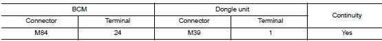
2.Check dongle unit circuit
- Turn ignition switch OFF.
- Disconnect BCM connector and dongle unit connector.
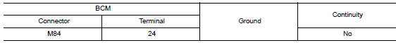
- Check continuity between BCM harness connector and dongle unit harness connector.
- Check continuity between BCM harness connector and ground.
Is the inspection result normal?
Yes >> go to 3.
No >> repair or replace harness.
3.Check dongle unit ground circuit
Check continuity between dongle unit harness connector and ground.
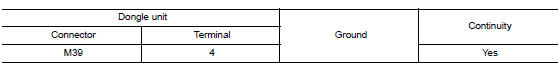
Is the inspection result normal? Yes >> replace dongle unit.
No >> repair or replace harness.
B2198 nats antenna amp.
Dtc logic
Dtc detection logic
| Dtc no. | Trouble diagnosis name | Dtc detecting condition | Possible cause |
| B2198 | Nats antenna amp | Inactive communication between nats antenna amp. And bcm is detected when bcm enters in the low power consumption mode (bcm sleep condition) |
|
Dtc confirmation procedure
1.Perform dtc confirmation procedure
- Make the conditions that bcm enters in the low power consumption mode (bcm
sleep condition).
Refer to bcs-8, "body control system : system description".
- Turn ignition switch on.
- Check dtc in self diagnostic result mode of bcm using consult.
Is dtc detected? Yes >> go to sec-71, "diagnosis procedure".
No >> inspection end.
Diagnosis procedure
Regarding Wiring Diagram information, refer to SEC-39, "Wiring Diagram".
1.Check fuse
- Turn power switch off.
- Check that the following fuse in ipdm e/r is not blown.

Is the inspection result normal? Yes >> go to 2.
No >> replace the blown fuse after repairing the cause of blowing.
2.Check nats antenna amp. Power supply
- Disconnect NATS antenna amp. connector.
- Check voltage between nats antenna amp. Harness connector and ground.
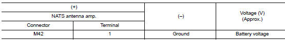
Is the inspection result normal? Yes >> go to 4.
No >> go to 3.
3.Check nats antenna amp. Power supply circuit
- Disconnect ipdm e/r connector.
- Check continuity between ipdm e/r harness connector and nats antenna amp. Connector.
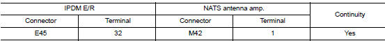
Is the inspection result normal? Yes >> replace ipdm e/r. Refer to pcs-30, "removal and installation".
No >> repair or replace harness.
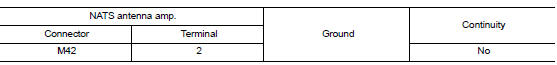
4.Check nats antenna amp. Ground circuit
Check continuity between nats antenna amp. Harness connector and ground.
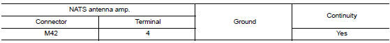
Is the inspection result normal? Yes >> go to 5.
No >> repair or replace harness.
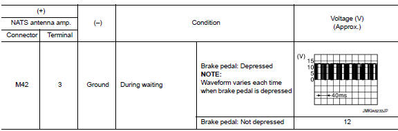
5.Check nats antenna amp. Communication signal 1
Check voltage signal between nats antenna amp. Harness connector and ground using an oscilloscope.
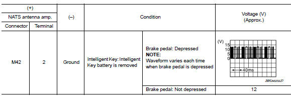
Is the inspection result normal? Yes >> go to 7.
No >> go to 6.
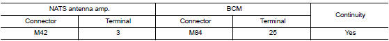
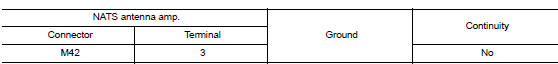
6.Check nats antenna amp. Output signal circuit 1
- Disconnect bcm connector.
- Check continuity between nats antenna amp. Harness connector and bcm connector.
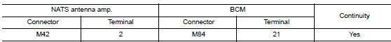
- Check continuity between nats antenna amp. Harness connector and ground.
Is the inspection result normal? Yes >> go to 9.
No >> repair or replace harness.
7.Check nats antenna amp. Communication signal 2
Check voltage signal between nats antenna amp. Harness connector and ground using an oscilloscope.
Is the inspection result normal? YES >> Replace NATS antenna amp. Refer to SEC-135, "Removal and Installation".
NO >> GO TO 8.
8.Check nats antenna amp. Output signal circuit 2
- Disconnect BCM connector.
- Check continuity between nats antenna amp. Harness connector and bcm connector.
- Check continuity between nats antenna amp. Harness connector and ground.
Is the inspection result normal? Yes >> go to 9.
No >> repair or replace harness.
9.Replace BCM
- Replace BCM. Refer to BCS-73, "Removal and Installation".
- Perform initialization of bcm and registration of all intelligent keys using consult.
>> Inspection end
B2555 stop lamp
Dtc logic
Dtc detection logic
| Dtc no. | Trouble diagnosis name | Dtc detecting condition | Possible cause |
| B2555 | STOP LAMP CIRCUIT | Bcm makes a comparison between the upper voltage and lower voltage of stop lamp switch. It judges from their values to detect the malfunctioning circuit. |
|
Dtc confirmation procedure
1.Perform dtc confirmation procedure
- Depress brake pedal and wait 1 second or more.
- Check DTC in Self Diagnostic Result mode of BCM using CONSULT.
Is dtc detected? Yes >> go to sec-74, "diagnosis procedure".
No >> inspection end.
Diagnosis procedure
Regarding Wiring Diagram information, refer to SEC-39, "Wiring Diagram".
1.Check stop lamp switch input signal 1
- Turn ignition switch off.
- Disconnect BCM connector.
- Check voltage between bcm harness connector and ground.v
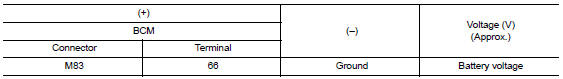
Is the inspection normal? Yes >> go to 2.
No-1 >> check 10 a fuse [no. 30, Located in the fuse block (j/b)].
No-2 >> check harness for open or short between bcm and fuse.
2.Check stop lamp switch power supply circuit
- Disconnect stop lamp switch connector.
- Check voltage between stop lamp switch harness connector and ground.
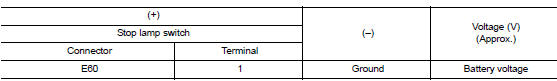
Is the inspection result normal? YES >> GO TO 3.
NO >> Check harness for open or short between stop lamp switch and fuse.
3.Check stop lamp switch input signal 2
- Connect stop lamp switch connector.
- Check voltage between bcm harness connector and ground.
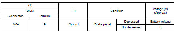
Is the inspecting result normal? Yes >> go to 4.
No >> go to 5.
4.Replace bcm
- Replace bcm. Refer to bcs-73, "removal and installation".
- Perform initialization of bcm and registration of all intelligent keys using consult.
>> Inspection end.
5.Check stop lamp switch circuit
- Disconnect stop lamp switch connector.
- Check continuity between stop lamp switch harness connector and BCM harness connector.
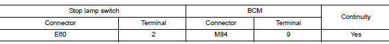
- Check continuity between stop lamp switch harness connector and ground.
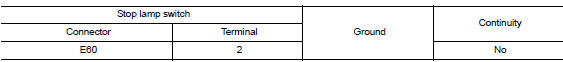
Is the inspection result normal? YES >> GO TO 6.
NO >> Repair or replace harness.
6.Check stop lamp switch
Refer to sec-75, "component inspection".
Is the inspection result normal? Yes >> go to 7.
No >> replace stop lamp switch. Refer to br-22, "exploded view".
7.Check intermittent incident
Refer to gi-39, "intermittent incident".
>> Inspection end.
Component inspection
1.Check stop lamp switch
- Turn ignition switch off
- Disconnect stop lamp switch connector.
- Check continuity between stop lamp switch terminals.
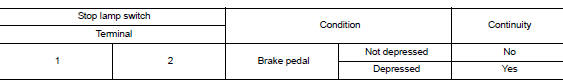
Is the inspection result normal? Yes >> inspection end.
No >> replace stop lamp switch. Refer to br-22, "exploded view".
B2556 push-button ignition switch
Dtc logic
Dtc detection logic
| Dtc no. | Trouble diagnosis name | Dtc detecting condition | Possible cause |
| B2556 | Eng start sw | Bcm detects the push-button ignition switch stuck at on for 100 seconds or more. |
|
Dtc confirmation procedure
1.Perform dtc confirmation procedure
- Press push-button ignition switch under the following condition.
- Brake pedal: not depressed
- Release push-button ignition switch and wait 100 seconds or more.
- Check dtc in self diagnostic result mode of bcm using consult.
Is dtc detected? Yes >> go to sec-77, "diagnosis procedure".
No >> inspection end.
Diagnosis procedure
Regarding wiring diagram information, refer to sec-39, "wiring diagram".
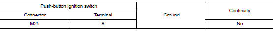
1.Check push-button ignition switch input signal
- Turn ignition switch off.
- Disconnect push-button ignition switch connector.
- Check voltage between push-button ignition switch harness connector and ground.
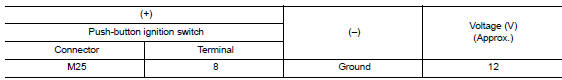
Is the inspection result normal? Yes >> go to 4.
No >> go to 2.
2.Check push-button ignition switch circuit
- Disconnect bcm connector and ipdm e/r connector.
- Check continuity between push-button ignition switch harness connector and bcm harness connector.
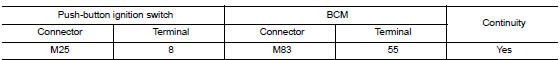
- Check continuity between push-button ignition switch harness connector and ground.
Is the inspection result normal? YES >> GO TO 3.
NO >> Repair or replace harness.
3.Replace bcm
- Replace bcm. Refer to bcs-73, "removal and installation".
- Perform initialization of bcm and registration of all intelligent keys using consult.
>> Inspection End.
4.Check push-button ignition switch ground circuit
Check continuity between push-button ignition switch harness connector and ground.
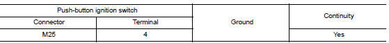
Is the inspection result normal? Yes >> go to 5.
No >> repair or replace harness.
5.Check push-button ignition switch
Refer to sec-78, "component inspection".
Is the inspection result normal? Yes >> go to 6.
No >> replace push-button ignition switch. Refer to sec-136, "removal and installation".
6.Check intermittent incident
Refer to gi-39, "intermittent incident".
>> Inspection end.
Component inspection
1.Check push-button ignition switch
- Turn ignition switch off.
- Disconnect push-button ignition switch connector.
- Check continuity between push-button ignition switch terminals.
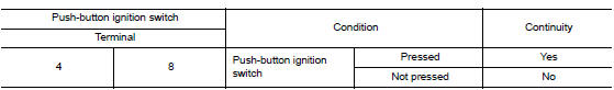
Is the inspection result normal? Yes >> inspection end.
No >> replace push-button ignition switch. Refer to sec-136, "removal and installation".
B2557 vehicle speed
Dtc logic
Dtc detection logic
Note:
- If dtc b2557 is displayed with dtc u1000, first perform the trouble diagnosis for dtc u1000. Refer to bcs-63, "dtc logic".
- If dtc b2557 is displayed with dtc u1010, first perform the trouble diagnosis for dtc u1010. Refer to bcs-64, "dtc logic".
| Dtc no. | Trouble diagnosis name | Dtc detecting condition | Possible causes |
| B2557 | Vehicle speed | Bcm detects one of the following conditions for 10
seconds continuously.
|
|
Dtc confirmation procedure
1.Perform dtc confirmation procedure
- Start engine and wait 10 seconds or more.
- Drive the vehicle at a vehicle speed of 10 km/h (6.2 Mph) or more for 10 seconds or more.
- Check dtc in self diagnostic result mode of bcm using consult.
Is dtc detected? Yes >> go to sec-79, "diagnosis procedure".
No >> inspection end.
Diagnosis procedure
1.Check dtc of “abs actuator and electric unit (control unit)”
Check dtc in self diagnostic result mode of abs using consult.
Is dtc detected? Yes >> perform the trouble diagnosis related to the detected dtc. Refer to brc-43, "dtc index".
No >> go to 2.
2.Check dtc of combination meter
Check dtc in self diagnostic result mode of meter/m&a using consult.
Is dtc detected? Yes >> perform the trouble diagnosis related to the detected dtc. Refer to mwi-26, "dtc index".
No >> go to 3.
3.Check intermittent incident
Refer to GI-39, "Intermittent Incident".
>> Inspection End.
B2601 shift position
Dtc logic
Dtc detection logic
Note:
- If dtc b2601 is displayed with dtc u1000, first perform the trouble diagnosis for dtc u1000. Refer to bcs-63, "dtc logic".
- If dtc b2601 is displayed with dtc u1010, first perform the trouble diagnosis for dtc u1010. Refer to bcs-64, "dtc logic".
| Dtc no. | Trouble diagnosis name | Dtc detecting condition | Possible cause |
| B2601 | SHIFT P SIGNAL | When there is a difference between p range signal from cvt shift selector (park position switch) and p position signal from ipdm e/r (can). |
|
Dtc confirmation procedure
1.Perform dtc confirmation procedure
- Shift the selector lever to the park (p) position.
- Turn ignition switch on and wait 2 seconds or more.
- Shift the selector lever to any position other than park (p) and wait 2 seconds or more.
- Check dtc in self diagnostic result mode of bcm using consult.
Is DTC detected? YES >> Go to SEC-80, "Diagnosis Procedure".
NO >> Inspection End.
Diagnosis procedure
Regarding wiring diagram information, refer to sec-39, "wiring diagram".
1.Check cvt shift selector circuit (bcm)
- Turn ignition switch OFF
- Disconnect cvt shift selector (park position switch) connector.
- Disconnect bcm connector
- Check continuity between CVT shift selector (park position switch) harness connector and BCM harness connector.
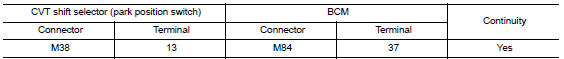
- Check continuity between cvt shift selector (park position switch) harness connector and ground.
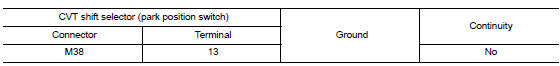
Is the inspection result normal? Yes >> go to 2.
No >> repair or replace harness.
2.Check cvt shift selector circuit (ipdm e/r)
- Disconnect ipdm e/r connector.
- Check continuity between CVT shift selector (park position switch) harness connector and IPDM E/R harness connector.
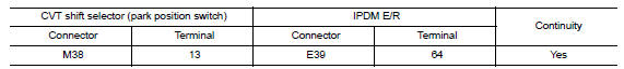
Is the inspection result normal? Yes >> go to 3.
No >> repair or replace harness.
3.Replace bcm
- Replace bcm. Refer to bcs-73, "removal and installation".
- Perform initialization of bcm and registration of all intelligent keys using consult.
- Perform dtc confirmation procedure for dtc b2601. Refer to sec-80, "dtc logic".
Is DTC B2601 detected again? YES >> Replace IPDM E/R. Refer to PCS-30, "Removal and Installation".
NO >> Inspection End.
B2602 shift position
Dtc logic
Dtc detection logic
Note:
- If dtc b2602 is displayed with dtc u1000, first perform the trouble diagnosis for dtc u1000. Refer to bcs-63, "dtc logic".
- If dtc b2602 is displayed with dtc u1010, first perform the trouble diagnosis for dtc u1010. Refer to bcs-64, "dtc logic".
| Dtc no. | Trouble diagnosis name | Dtc detecting condition | Possible cause |
| B2602 | SHIFT P DIAG | Bcm detects the following status for 10 seconds.
|
|
Dtc confirmation procedure
1.Perform dtc confirmation procedure
- Start engine
- Drive vehicle at a speed of 4 km/h (2.5 Mph) or more for 10 seconds or more.
- Check dtc in self diagnostic result mode of bcm using consult.
Is dtc detected? Yes >> go to sec-82, "diagnosis procedure".
No >> inspection end.
Diagnosis procedure
Regarding wiring diagram information, refer to sec-39, "wiring diagram".
1.Check dtc of abs actuator and electric unit (control unit)
Check dtc in self diagnostic result mode of abs using consult.
Is dtc detected? Yes >> perform the trouble diagnosis related to the detected dtc. Refer to brc-43, "dtc index".
No >> go to 2.
2.Check dtc of combination meter
Check dtc in self diagnostic result mode of meter/m&a using consult.
Is dtc detected? Yes >> perform the trouble diagnosis related to the detected dtc. Refer to mwi-26, "dtc index".
No >> go to 3.
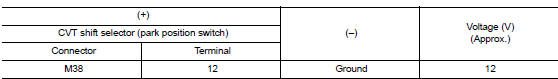
3.Check cvt shift selector power supply
- Turn ignition switch off.
- Disconnect cvt shift selector (park position switch) connector.
- Turn ignition switch ON.
- Check voltage between cvt shift selector (park position switch) harness connector and ground.
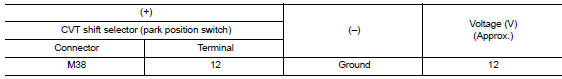
Is the inspection result normal? YES >> GO TO 6.
NO >> GO TO 4.
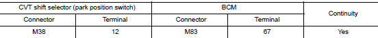
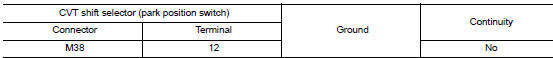
4.Check cvt shift selector power supply circuit
- Turn ignition switch off.
- Disconnect bcm connector.
- Check continuity between cvt shift selector (park position switch) harness connector and bcm harness connector.
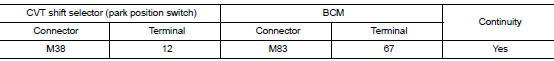
- Check continuity between cvt shift selector (park position switch) harness connector and ground.
Is the inspection result normal? Yes >> go to 5.
No >> repair or replace harness.
5.Replace bcm
- Replace bcm. Refer to bcs-73, "removal and installation".
- Perform initialization of bcm and registration of all intelligent keys using consult.
>> Inspection end.
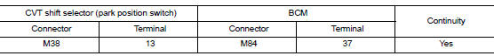
6.Check cvt shift selector circuit
- Turn ignition switch off.
- Disconnect bcm connector and ipdm e/r connector.
- Check continuity between CVT shift selector (park position switch) harness connector and BCM harness connector.
- Check continuity between cvt shift selector (park position switch) harness connector and ground.
Is the inspection result normal? Yes >> go to 7.
No >> repair or replace harness.
7.Check cvt shift selector (park position switch)
Refer to sec-84, "component inspection".
Is the inspection result normal? Yes >> go to 8.
No >> replace cvt shift selector. Refer to tm-253, "removal and installation".
8.Check intermittent incident
Refer to gi-39, "intermittent incident".
>> Inspection end.
Component inspection
1.Check cvt shift selector (park position switch)
- Turn ignition switch off.
- Disconnect cvt shift selector connector.
- Check continuity between cvt shift selector (park position switch) terminals.
Is the inspection result normal? Yes >> inspection end.
No >> replace cvt shift selector. Refer to tm-253, "removal and installation".
B2603 shift position
Dtc logic
Dtc detection logic
Note:
If dtc b2603 is displayed with dtc b2601, first perform the trouble diagnosis for dtc b2601. Refer to sec-80, "dtc logic".
| Dtc no. | Trouble diagnosis name | Dtc detecting condition | Possible causes |
| B2603 | SHIFT POSITION | Bcm detects the following status when ignition
switch is in the on position.
|
|
Dtc confirmation procedure
1.Perform dtc confirmation procedure 1
- Shift the selector lever to the Park (P) position
- Turn ignition switch ON and wait 1 second or more.
- Check dtc in self diagnostic result mode of bcm using consult.
Is DTC detected? YES >> Go to SEC-85, "Diagnosis Procedure".
NO >> GO TO 2.
2.Perform dtc confirmation procedure 2
- Shift the selector lever to the position other than park (p) and neutral (n), and wait 1 second or more.
- Check dtc in self diagnostic result mode of bcm using consult.
Is dtc detected? Yes >> go to sec-85, "diagnosis procedure".
No >> inspection end.
Diagnosis procedure
Regarding wiring diagram information, refer to sec-39, "wiring diagram".
1.Inspection start
Perform inspection in accordance with procedure that confirms dtc.
Which procedure confirms dtc? Dtc confirmation procedure 1>>go to 2.
Dtc confirmation procedure 2>>go to 8.
2.Check fuse
- Turn power switch off.
- Check that the following fuse in ipdm e/r is not blown.

Is the inspection result normal?
YES >> GO TO 3.
NO >> Replace the blown fuse after repairing the cause of blowing.
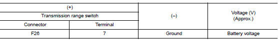
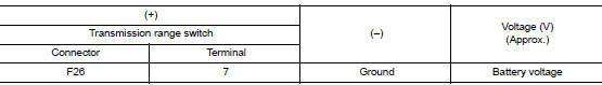
3.Check transmission range switch power supply
- Disconnect transmission range switch connector.
- Turn ignition switch ON.
- Check voltage between transmission range switch harness connector and ground.
Is the inspection result normal? Yes >> go to 5.
No >> go to 4.
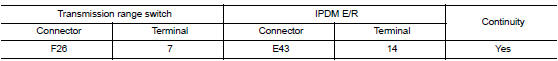
4.Check transmission range switch power supply circuit
- Turn ignition switch off.
- Disconnect IPDM E/R connector.
- Check continuity between transmission range switch harness connector and ipdm e/r harness connector.
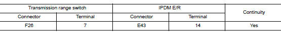
Is the inspection result normal? Yes >> replace ipdm e/r. Refer to pcs-30, "removal and installation".
No >> repair or replace harness.
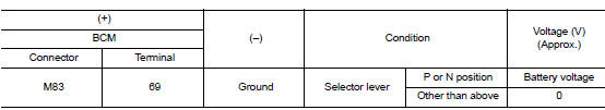
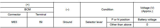
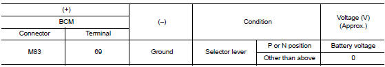
5.Check bcm input signal
- Turn ignition switch off.
- Connect transmission range switch harness connector.
- Turn ignition switch ON.
- Check voltage between BCM harness connector and ground.
Is the inspection result normal? Yes >> go to 13.
No >> go to 6.
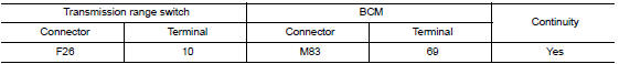
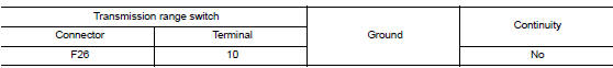
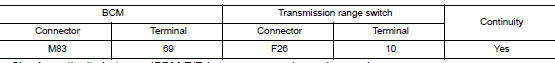
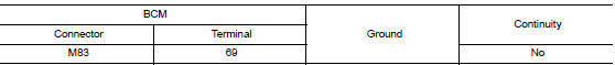
6.Check bcm input signal circuit
- Turn ignition switch off.
- Disconnect transmission range switch connector.
- Disconnect bcm connector.
- Check continuity between transmission range switch harness connector and bcm harness connector.
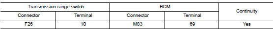
Is the inspection result normal?
YES >> GO TO 7.
NO >> Repair or replace harness.
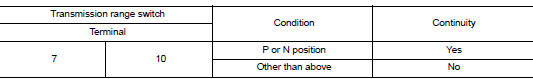
7.CHECK TRANSMISSION RANGE SWITCH
Refer to SEC-88, "Component Inspection (Transmission Range Switch)".
Is the inspection result normal? YES >> GO TO 12.
NO >> Replace transmission range switch.
8.Check CVT Shift selector power supply
- Turn ignition switch off.
- Disconnect cvt shift selector (park position switch) connector.
- Turn ignition switch on.
- Check voltage between cvt shift selector (park position switch) harness connector and ground.
Is the inspection result normal? YES >> GO TO 10.
NO >> GO TO 9.
9.Check cvt shift selector power supply circuit
- Turn ignition switch off.
- Disconnect bcm connector.
- Check continuity between cvt shift selector (park position switch) harness connector and bcm harness connector.
- Check continuity between cvt shift selector (park position switch) harness connector and ground.
Is the inspection result normal? Yes >> go to 12.
No >> repair or replace harness.
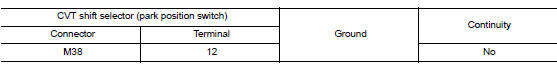
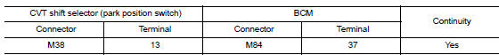
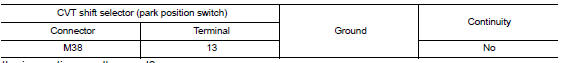
10.Check cvt shift selector circuit
- Turn ignition switch off.
- Disconnect bcm connector.
- Check continuity between cvt shift selector (park position switch) harness connector and bcm harness connector.
- Check continuity between CVT shift selector (park position switch) harness connector and ground.
Is the inspection result normal? Yes >> go to 11.
No >> repair or replace harness.
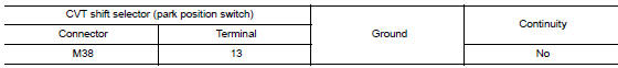
11.Check cvt shift selector (park position switch)
Refer to sec-88, "component inspection [cvt shift selector (park position switch)]".
Is the inspection result normal? Yes >> go to 13.
No >> replace cvt shift selector. Refer to tm-253, "removal and installation".
12.Check intermittent incident
Refer to gi-39, "intermittent incident".
>> Inspection end.
13.Replace bcm
- Replace BCM. Refer to BCS-73, "Removal and Installation".
- Perform initialization of BCM and registration of all Intelligent Keys using CONSULT.
>> Inspection End.
Component inspection (transmission range switch)
1.Check transmission range switch
- Turn ignition switch off
- Disconnect transmission range switch connector.
- Check continuity between transmission range switch terminals.
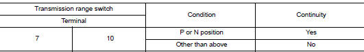
Is the inspection result normal? Yes >> inspection end
NO >> Replace transmission range switch.
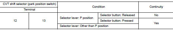
Component inspection [cvt shift selector (park position switch)]
1.Check cvt shift selector (detention switch)
- Turn ignition switch OFF.
- Disconnect cvt shift selector connector.
- Check continuity between cvt shift selector (park position switch) terminals.
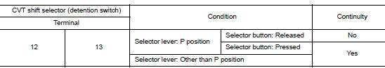
Is the inspection result normal?
YES >> Inspection End.
NO >> Replace CVT shift selector. Refer to TM-253, "Removal and Installation".
B2604 SHIFT POSITION
DTC Logic
DTC DETECTION LOGIC
NOTE:
- If DTC B2604 is displayed with DTC U1000, first perform the trouble diagnosis for DTC U1000. Refer to BCS-63, "DTC Logic".
- If DTC B2604 is displayed with DTC U1010, first perform the trouble diagnosis for DTC U1010. Refer to BCS-64, "DTC Logic".
| DTC No. | Trouble diagnosis name | DTC detecting condition | Possible cause |
| B2604 | SHIFT PN DIAG CAN | The following states are detected for 5 seconds
while ignition switch is ON
|
|
DTC CONFIRMATION PROCEDURE
1.Perform dtc confirmation procedure
- Shift the selector lever to the park (p) position.
- Turn ignition switch on and wait 5 seconds or more.
- Shift the selector lever to the neutral (n) position and wait 5 seconds or more.
- Shift the selector lever to any position other than park (p) and neutral (n), and wait 5 seconds or more.
- Check DTC in Self Diagnostic Result mode of BCM using CONSULT.
Is dtc detected? Yes >> go to sec-90, "diagnosis procedure".
No >> inspection end.
Diagnosis procedure
Regarding Wiring Diagram information, refer to SEC-39, "Wiring Diagram".
1.Check dtc of tcm
Check dtc in self diagnostic result mode of tcm using consult.
Is dtc detected? Yes >> perform the trouble diagnosis related to the detected dtc. Refer to tm-126, "dtc index".
No >> go to 2.
2.Check fuse
- Turn power switch off.
- Check that the following fuse in ipdm e/r is not blown.

Is the inspection result normal? YES >> GO TO 3.
NO >> Replace the blown fuse after repairing the cause of blowing.
3.Check transmission range switch power supply
- Disconnect transmission range switch connector.
- Turn ignition switch on.
- Check voltage between transmission range switch harness connector and ground.
Is the inspection result normal? Yes >> go to 5.
No >> go to 4.
4.Check transmission range switch power supply circuit
- Turn ignition switch off.
- Disconnect ipdm e/r connector.
- Check continuity between transmission range switch harness connector and IPDM E/R harness connector.
Is the inspection result normal? YES >> Replace IPDM E/R. Refer to PCS-30, "Removal and Installation".
NO >> Repair or replace harness.
5.Check bcm input signal
- Turn ignition switch off.
- Reconnect transmission range switch connector.
- Turn ignition switch on.
- Check voltage between bcm harness connector and ground.
Is the inspection result normal? Yes >> go to 9.
No >> go to 6.
6.Check bcm input signal circuit
- Turn ignition switch off.
- Disconnect transmission range switch connector.
- Disconnect BCM connector.
- Check continuity between transmission range switch harness connector and bcm harness connector.
- Check continuity between transmission range switch harness connector and ground.
Is the inspection result normal?
Yes >> go to 7.
No >> repair or replace harness.
7.Check transmission range switch
Refer to sec-92, "component inspection".
Is the inspection result normal? Yes >> go to 8.
No >> replace transmission range switch.
8.Check intermittent incident
Refer to gi-39, "intermittent incident".
>> Inspection end.
9.Replace bcm
- Replace bcm. Refer to bcs-73, "removal and installation".
- Perform initialization of bcm and registration of all intelligent keys using consult.
>> Inspection end.
Component inspection
1.Check transmission range switch
- Turn ignition switch OFF.
- Disconnect transmission range switch connector.
- Check continuity between transmission range switch terminals.
Is the inspection result normal? Yes >> inspection end.
No >> replace transmission range switch.
B2605 shift position
Dtc logic
Dtc detection logic
Note:
- If dtc b2605 is displayed with dtc u1000, first perform the trouble diagnosis for dtc u1000. Refer to bcs-63, "dtc logic".
- If dtc b2605 is displayed with dtc u1010, first perform the trouble diagnosis for dtc u1010. Refer to bcs-64, "dtc logic".
| Dtc no. | Trouble diagnosis name | Dtc detecting condition | Possible cause |
| B2605 | Shift pn diag ipdm | When ignition switch is ON, P/N position signal input from transmission range switch and P/N position signal (CAN) input from IPDM E/R do not match. |
|
Dtc confirmation procedure
1.Perform dtc confirmation procedure
- Shift the selector lever to the park (p) position.
- Turn ignition switch on and wait 1 second or more.
- Shift the selector lever to the neutral (n) position and wait 1 second or more.
- Shift the selector lever to any position other than park (p) and neutral (n), and wait 1 second or more.
- Check dtc in self diagnostic result mode of bcm using consult.
Is dtc detected? Yes >> go to sec-93, "diagnosis procedure".
No >> inspection end.
Diagnosis procedure
Regarding wiring diagram information, refer to sec-39, "wiring diagram".
1.Check ipdm e/r input signal
- Turn ignition switch on.
- Check voltage between ipdm e/r harness connector and ground.
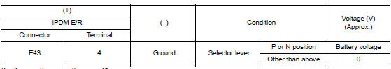
Is the inspection result normal? Yes >> go to 3.
No >> go to 2.
2.Check ipdm e/r input signal circuit
- Turn ignition switch off.
- Disconnect ipdm e/r connector.
- Disconnect transmission range switch connector.
- Check continuity between ipdm e/r harness connector and transmission range switch harness connector.
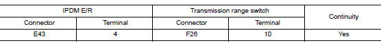
- Check continuity between ipdm e/r harness connector and ground.
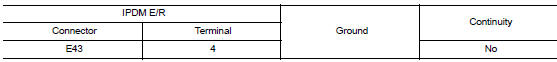
Is the inspection result normal? Yes >> go to 5.
No >> repair or replace harness.
3.Check bcm input signal
Check voltage between bcm harness connector and ground.
Is the inspection result normal? Yes >> go to 5.
No >> go to 4.
4.Check bcm input signal circuit
- Turn ignition switch off.
- Disconnect bcm connector.
- Disconnect transmission range switch connector.
- Check continuity between bcm harness connector and transmission range switch harness connector.
- Check continuity between ipdm e/r harness connector and ground.
Is the inspection result normal? Yes >> go to 5.
No >> repair or replace harness.
5.Replace bcm
- Replace bcm. Refer to bcs-73, "removal and installation".
- Perform initialization of bcm using consult.
- Perform dtc confirmation procedure for b2605. Refer to sec-93, "dtc logic".
Is dtc b2605 detected again? Yes >> replace ipdm e/r. Refer to pcs-30, "removal and installation".
No >> inspection end.
B2608 starter relay
Dtc logic
Dtc detection logic
Note:
- If DTC B2608 is displayed with DTC U1000, first perform the trouble diagnosis for DTC U1000. Refer to BCS-63, "DTC Logic".
- If DTC B2608 is displayed with DTC U1010, first perform the trouble diagnosis for DTC U1010. Refer to BCS-64, "DTC Logic".
- If DTC B2608 is displayed with other DTC (BCM), first perform the trouble diagnosis for other DTC detected.
| Dtc no. | Trouble diagnosis name | Dtc detecting condition | Possible cause |
| B2608 | Starter relay | BCM outputs starter relay OFF signal but BCM receives starter relay ON signal from IPDM E/R (CAN). |
|
 Basic inspection
Diagnosis and repair work flow
Work flow
OVERALL SEQUENCE
DETAILED FLOW
1.GET INFORMATION FOR SYMPTOM
Get detailed information from the customer about the symptom (the
condition and the ...
 Symptom diagnosis
Engine does not start when intelligent key is inside of vehicle
Description
Engine does not start when push-button ignition switch is pressed while
carrying intelligent key.
Note:
Check that ...
Other materials:
Removal and installation
Ipdm e/r
Exploded view
Ipdm e/r
IPDM E/R cover A
Ipdm e/r cover b
Removal and installation
Caution:
Ipdm e/r integrated relays are not serviceable and must not be removed
from unit.
Removal
Remove inlet air duct (upper). Refer to em-25, "removal and
installation" ...
Exhaust manifold
Exploded View
CALIFORNIA
Air fuel ratio sensor
Exhaust manifold heat shield (upper)
Exhaust manifold and three way catalyst
Exhaust manifold heat shield (rear)
Exhaust manifold heat shield (front)
Exhaust manifold gasket
Cylinder head
EXCEPT CALIFORNIA
Air fuel ratio ...
P0712 Transmission fluid temperature sensor A
DTC Logic
DTC DETECTION LOGIC
DTC
CONSULT screen terms
(Trouble diagnosis content)
DTC detection condition
Possible causes
P0712
FLUID TEMP SENSOR A
(Transmission Fluid Temperature
Sensor A Circuit Low)
The CVT fluid temperature identified by the
TCM is 1 ...
