Nissan Sentra Service Manual: Diagnosis system (ipdm e/r) (without intelligent key system)
Diagnosis Description
AUTO ACTIVE TEST
Description
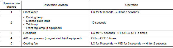
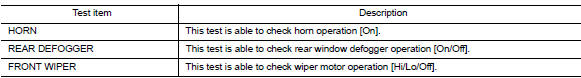
In auto active test, the IPDM E/R sends a drive signal to the following systems to check their operation.
- Front wiper (LO, HI)
- Parking lamp
- License plate lamp
- Tail lamp
- Front fog lamp (if equipped)
- Headlamp (LO, HI)
- A/C compressor (magnet clutch) (if equipped)
- Cooling fan
Operation Procedure
NOTE:
Never perform auto active test in the following conditions.
- Passenger door is open
- CONSULT is connected
- Close the hood and lift the wiper arms from the windshield. (Prevent windshield damage due to wiper operation)
NOTE:
When auto active test is performed with hood opened, sprinkle water on windshield beforehand.
- Turn the ignition switch OFF.
- Turn the ignition switch ON, and within 20 seconds, press the driver door switch 10 times. Then turn the ignition switch OFF.
- Turn the ignition switch ON within 10 seconds. After that the horn sounds once and the auto active test starts.
- After a series of the following operations is repeated 3 times, auto active test is completed.
NOTE:
- When auto active test has to be cancelled halfway through test, turn the ignition switch OFF.
- When auto active test is not activated, door switch may be the cause. Check door switch. Refer to DLK-255, "Component Inspection".
Inspection in Auto Active Test
When auto active test is actuated, the following operation sequence is repeated 3 times.
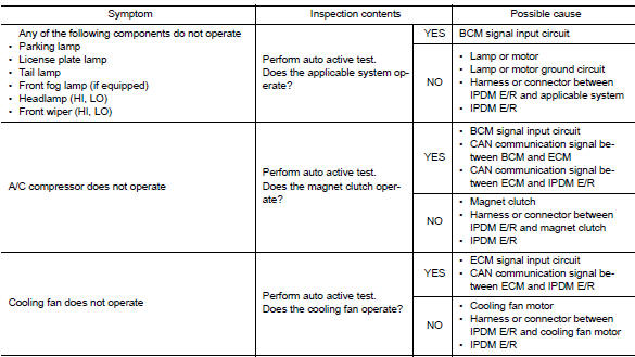
Diagnosis Chart in Auto Active Test
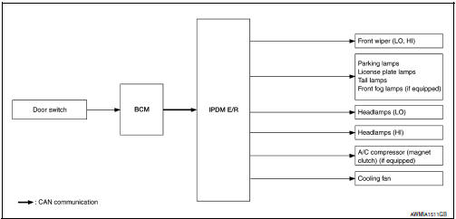
- IPDM E/R starts the auto active test with the door switch signals
transmitted by BCM via CAN communication.
Therefore, the CAN communication line between IPDM E/R and BCM is considered normal if the auto active test starts successfully.
- The auto active test facilitates troubleshooting if any systems controlled by IPDM E/R cannot be operated.
Diagnosis Chart in Auto Active Test
CONSULT Function (IPDM E/R)
APPLICATION ITEM
CONSULT performs the following functions via CAN communication with IPDM E/R.
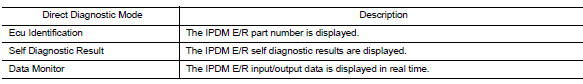
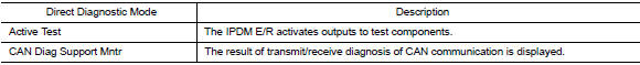
ECU IDENTIFICATION
The IPDM E/R part number is displayed.
SELF DIAGNOSTIC RESULT
Refer to PCS-48, "DTC Index".
DATA MONITOR

ACTIVE TEST

CAN DIAG SUPPORT MNTR
Refer to LAN-13, "CAN Diagnostic Support Monitor".
 Diagnosis system (ipdm e/r) (with intelligent key system)
Diagnosis Description
AUTO ACTIVE TEST
Description
In auto active test, the IPDM E/R sends a drive signal to the following
systems to check their operation.
Front wiper (LO, HI)
Parking la ...
 Ecu diagnosis information
Bcm, ipdm e/r
List of ECU Reference
WITH INTELLIGENT KEY SYSTEM
WITHOUT INTELLIGENT KEY SYSTEM
...
Other materials:
System description
Component parts
Component parts location
Instrument lower finisher
Eco mode switch
The eco mode switch is installed to the instrument lower finisher.
When the ECO mode indicator lamp on the combination meter is
OFF and the ECO mode switch is pressed, the ECO mode is
active and ...
Making a call
To make a call from a phone connected to the
vehicle’s Bluetooth® Hands-Free Phone System:
NOTE:
Available commands different if system is
in Manual Control mode. See “Manual Control”
in this section for more information.
Press the button.
The system will prompt you for a command. ...
Pregnant women
NISSAN recommends that pregnant women use
seat belts. The seat belt should be worn snug and
always position the lap belt as low as possible
around the hips, not the waist. Place the shoulder
belt over your shoulder and across your chest.
Never run the lap/shoulder belt over your abdominal
ar ...
