Nissan Sentra B18 (2020-2025) Service Manual: Diagnosis System (combination Meter)
On Board Diagnosis Function
On Board Diagnosis Function
ON BOARD DIAGNOSIS
The following meter functions can be checked during Combination Meter Self-Diagnosis Mode:
-
Pointer sweep of speedometer, tachometer and gauges.
-
Illumination of LCD color patterns for meter displays.
-
Illumination of all lamps/LEDs that are controlled by the combination meter.
-
Error code
METHOD OF STARTING
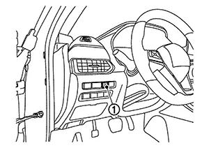
How to Initiate Self-Diagnosis Mode
-
Ignition switch OFF.
-
While pressing the trip reset switch (1), place ignition switch ON.
-
Keep pressing the trip reset switch for 1 seconds or more.
-
Press the trip reset switch at least 3 times. (Within 7 seconds after ignition switch ON.)
-
“Work instruction code” is indicated in the top portion of information display and self-diagnosis is started.
Note:
When on-board diagnosis does not start, check the following items and replace combination meter if the check results are normal.
-
Combination meter power supply and ground circuits. Refer to Diagnosis Procedure.
-
Trip reset switch signal circuits. Refer to Diagnosis Procedure.
-
-
The mode switches in the order shown below each time the trip reset switch is pressed.
Note:
-
If the trip reset switch is not operated for 20 seconds or more, the self-diagnosis mode is automatically cancelled.
-
The self-diagnosis mode is cancelled by ignition switch OFF.
-
The self-diagnosis mode is cancelled by engine speed 170 rpm or more.
-
|
Test order |
Test item |
Description |
|
|---|---|---|---|
|
1 |
Work instruction code |
This item is displayed, but not used. |
|
|
2 |
Spare parts No. |
||
|
Soft ware code |
|||
|
Flash rom No. |
|||
|
3 |
EEPROM code |
||
|
4 |
Hardware code |
||
|
5 |
PCB code |
||
|
6 |
Circuit check |
The pointer of the following items moves from 0 to MAX then from MAX to 0:
If any one of the pointers does not sweep, replace combination meter. |
|
|
7 |
Color check |
Performs the color check of the information display. |
|
|
8 |
Error code* |
Displays the error code of the following items:
|
|
|
9 |
Warning/indicator lamp check |
All warning/indicator lamp illuminate. Note:
Security indicator lamp are not illuminate. |
|
When the trip reset switch is pressed during the indication of "Test order 9", test item returns to "Test order 2".
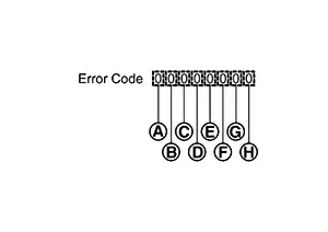
*: Error Code
|
Item |
Code |
Description |
Action to take/Reference |
|
|---|---|---|---|---|
|
|
Speedometer |
0 |
Normal |
— |
|
1 |
A Nissan Sentra vehicle speed signal can not be received from ECM. |
Select “Self Diagnostic Result” mode of “ENGINE”. Refer to DTC Index. |
||
|
2 |
A Nissan Sentra vehicle speed signal received from ECM is abnormal. (FFFFh) |
|||
|
|
Tachometer |
0 |
Normal |
— |
|
1 |
An engine speed signal cannot be received from ECM. |
Select “Self Diagnostic Result” mode of “ENGINE”. Refer to DTC Index. |
||
|
|
Fuel gauge |
0 |
Normal |
— |
|
1 |
Fuel gauge circuit is short. |
Refer to Component Function Check. |
||
|
2 |
Fuel gauge circuit is open. |
|||
|
|
Engine coolant temperature gauge |
0 |
Normal |
— |
|
1 |
An engine coolant temperature signal cannot be received from ECM. |
Select “Self Diagnostic Result” mode of “ENGINE”. Refer to DTC Index. |
||
|
|
Steering switch |
0 |
Normal |
— |
|
1 |
When judging that the steering switch signal circuit is short-circuited for 5 minutes or more. |
Select “Self Diagnostic Result” mode of “METER/M&A.” Refer to DTC Index. |
||
|
|
— |
0 |
Displays “0” constantly. |
— |
|
|
— |
0 |
Displays “0” constantly. |
— |
|
|
— |
0 |
Displays “0” constantly. |
— |


Consult Function (meter/m&a)
CONSULT Function (METER/M&A)
APPLICATION ITEMS
CONSULT can perform the following diagnosis modes via CAN communication and the combination meter:
|
Diagnosis mode |
CGW Status |
Description |
||
|---|---|---|---|---|
|
Restricted Mode |
Diag Test Mode |
Open Mode |
||
|
Self Diagnostic Result |
Display |
Display |
Display |
Display non-network DTC which combination meter memorizes. |
|
CGW Information |
Display |
Display |
Display |
|
|
Data Monitor |
Display |
Display |
Display |
Displays combination meter input/output data in real time. |
|
ECU Identification |
Display |
Display |
Display |
Displays combination meter part number. |
|
Warning History |
Display |
Display |
Display |
Lighting history of the warning lamp and indicator lamp can be checked. |
|
Configuration |
Display |
Display |
Display |
|
|
Network-DTC |
Display |
Display |
Display |
Display network DTC which combination meter memorizes when performing "Diagnosis (All System)". |
|
CAN Diag Support Monitor* |
Display |
Display |
Display |
Note:
The mode is indicated, but not monitored. |
*: Displays when performing "Diagnosis (All System)".
CGW INFORMATION
Display the diagnosis mode which a user can perform in Diag Test mode/Open Mode by switching the CGW status from Restricted mode to Diag Test Mode/Open Mode.
For the method of switching CAN Gateway status, refer to CONSULT Function.
SELF DIAG RESULT
Refer to DTC Index.
Freeze frame data (FFD)
When DTC is detected, the following Nissan Sentra vehicle condition is recorded and it is displayed on the CONSULT screen.
|
Item name |
Display item |
|
|---|---|---|
|
ODO/TRIP METER |
Records an odometer value when DTC is detected.
|
|
|
DTC count |
Records the number of times DTC was detected. |
|
DATA MONITOR
Note:
The following table includes information (items) inapplicable to this Nissan Sentra vehicle. For information (items) applicable to this vehicle, refer to CONSULT display items.
Display Item List
X: Applicable|
Display item [Unit] |
MAIN SIGNALS |
Description |
|---|---|---|
|
SPEED METER [mph] or [km/h] |
X |
Value of Nissan Sentra vehicle speed signal received from ECM via CAN communication. |
|
SPEED OUTPUT [mph] or [km/h] |
X |
Nissan Sentra Vehicle speed signal value transmitted to other units via CAN communication. |
|
ODO OUTPUT [mi] or km] |
Odometer signal received from ABS actuator and electric unit (control unit) via CAN communication. |
|
|
TACHO METER [rpm] |
X |
Value of the engine speed signal received from ECM via CAN communication. |
|
FUEL METER [L] |
X |
Fuel level indicated on combination meter. |
|
W TEMP METER [°F] or [°C] |
X |
Value of engine coolant temperature signal is received from ECM via CAN communication. |
|
ABS W/L [On/Off] |
Status of ABS warning lamp detected from ABS warning lamp signal is received from ABS actuator and electric unit (control unit) via CAN communication. |
|
|
VDC/TCS IND [On/Off] |
Status of VDC OFF indicator lamp detected from VDC OFF indicator lamp signal is received from ABS actuator and electric unit (control unit) via CAN communication. |
|
|
SLIP IND [On/Off] |
Status of VDC warning lamp detected from VDC warning lamp signal received from ABS actuator and electric unit (control unit) via CAN communication. |
|
|
BRAKE W/L [On/Off] |
Status of brake warning lamp detected from brake warning lamp signal is received from ABS actuator and electric unit (control unit) via CAN communication and brake fluid level switch signal from brake fluid level switch. Note:
Displays “Off” if the brake warning lamp is illuminated when the valve check starts, the parking brake switch is turned ON or the brake fluid level switch is turned ON. |
|
|
DOOR W/L [On/Off] |
Status of door open warning detected from door switch signal received from BCM via CAN communication. |
|
|
TRUNK/GLAS-H [On/Off] |
Status of trunk open warning detected from trunk lid opener assembly (trunk lid switch) signal received from BCM via CAN communication. |
|
|
HI-BEAM IND [On/Off] |
Status of high beam indicator lamp detected from high beam status signal is received from BCM via CAN communication. |
|
|
TURN IND [On/Off] |
Status of turn signal indicator lamp detected from turn indicator signal is received from BCM via CAN communication. |
|
|
FR FOG IND [On/Off] |
Status of front fog lamp indicator lamp detected from front fog light status signal is received from BCM via CAN communication. |
|
|
LIGHT IND [On/Off] |
Status of position lamp indicator lamp detected from position light status signal is received from BCM via CAN communication. |
|
|
OIL W/L [On/Off] |
Status of engine oil pressure warning detected from engine oil pressure warning lamp signal is received from ECM via CAN communication. |
|
|
MIL [On/Off] |
Status of malfunction indicator lamp detected from malfunctioning indicator lamp signal is received from ECM via CAN communication. |
|
|
BA W/L [On/Off] |
Status of AEB warning lamp judged from AEB warning lamp signal received from ADAS control unit 2 via CAN communication. |
|
|
FUEL W/L [On/Off] |
Low fuel warning status detected by the identified fuel level. |
|
|
WASHER W/L [On/Off] |
Status of low washer fluid warning judged from washer level switch input to combination meter. |
|
|
AIR PRES W/L [On/Off] |
Status of low tire pressure warning lamp judged from low tire pressure lamp signal received from BCM via CAN communication. |
|
|
KEY G/Y W/L [On/Off] |
Status of Intelligent Key system malfunction detected from meter display signal is received from BCM via CAN communication. |
|
|
KEY KNOB W/L [Off] |
Note:
This item is displayed, but cannot be monitored. |
|
|
EPS W/L [On/Off] |
Status of EPS warning lamp detected from EPS warning lamp signal is received from EPS control unit via CAN communication. |
|
|
LANE W/L [On/Off] |
Status of lane departure warning lamp judged from lane departure warning lamp signal received from ADAS control unit 2 with CAN communication. |
|
|
CHAGE W/L [On/Off] |
Status of 12V battery charge warning lamp judged from battery warning request signal received from ECM or IPDM E/R via CAN communication. |
|
|
ECO MODE IND [On/Off] |
Status of ECO mode indicator lamp detected from ECO mode indicator lamp signal from BCM via CAN communication. |
|
|
REAR DEF SW [On/Off] |
Status of rear defogger switch. |
|
|
PKB SW [On/Off] |
Status of parking brake switch. |
|
|
BUCKLE SW [On/Off] |
Status of front seat belt buckle switch (driver side). |
|
|
BRAKE OIL SW [On/Off] |
Status of brake fluid level switch. |
|
|
ECO MODE SW [On/Off] |
Status of ECO mode switch. |
|
|
CHG CONCT DET [Off] |
Note:
This item is displayed, but cannot be monitored. |
|
|
LED LMP R OPEN [On/Off] |
Status of front combination lamp RH judged based on headlamp warning signal input from IPDM E/R via CAN communication. |
|
|
LED LMP L OPEN [On/Off] |
Status of front combination lamp LH judged based on headlamp warning signal input from IPDM E/R via CAN communication. |
|
|
DCA IND [Off] |
Note:
This item is displayed, but cannot be monitored. |
|
|
ACC TARGET [On/Off] |
Status of Nissan Sentra vehicle ahead detection indicator judged from meter display signal received from ADAS control unit 2 via CAN communication. |
|
|
ACC SET SPEED [mph/km/h/Off] |
Status of set Nissan Sentra vehicle speed indicator judged from meter display signal received from ADAS control unit 2 via CAN communication. |
|
|
ACC DISTANCE [Off, Short, Middle, Long] |
Status of set distance indicator judged from meter display signal received from ADAS control unit 2 via CAN communication. |
|
|
ACC OWN VHL [On/Off] |
Status of own Nissan Sentra vehicle indicator judged from meter display signal received from ADAS control unit 2 via CAN communication. |
|
|
ACC UNIT [On/Off] |
Status of display unit judged from meter display signal received from ADAS control unit 2 via CAN communication. |
|
|
SHIFT IND [P, R, N, D, L] |
Status of shift position indicator detected from shift position signal is received from TCM via CAN communication. |
|
|
DISTANCE [mi] or [km] |
Value of distance to empty calculated by combination meter. |
|
|
FUEL CAP W/L [On/Off] |
Status of fuel filler cap warning display detected from fuel filler cap warning display signal received from ECM via CAN communication. |
|
|
M RANGE SW [Off] |
Note:
This item is displayed, but cannot be monitored. |
|
|
NM RANGE SW [Off] |
Note:
This item is displayed, but cannot be monitored. |
|
|
AT SFT UP SW [Off] |
Note:
This item is displayed, but cannot be monitored. |
|
|
AT SFT DWN SW [Off] |
Note:
This item is displayed, but cannot be monitored. |
|
|
OUTSIDE TEMP [°F] or [°C] |
Ambient temperature value converted from ambient sensor signal received from ambient sensor. Note:
This may not match with the temperature value indicated on the information display. (Because the information display value is a corrected value from the ambient sensor input value.) |
|
|
FUEL LOW SIG [On/Off] |
Status of fuel level low warning signal to output to AV control unit via CAN communication. |
|
|
BUZZER [On/Off] |
X |
Buzzer status (in the combination meter) is detected from the buzzer output signal received from each unit via CAN communication and the warning output condition of the combination meter. |
|
STRG SW INPUT [SW1-SW12, NOT INPUT] |
Status of steering switch. |
|
|
BSW IND [WARN ON/BLINK/On/Off] |
Status of BSW system display detected from meter display signal is received from ADAS control unit 2 via CAN communication. |
|
|
LDP IND [Off] |
Note:
This item is displayed, but cannot be monitored. |
|
|
BATTERY CIRCUIT STATUS [NORMAL/OPEN] |
Status of fuse for shipping mode from shipping mode status signal received from BCM via CAN communication. |
|
|
PARKING ASSIST DSP [On/Off] |
Status of sonar display received from sonar control unit via CAN communication. |
|
|
PARKING ASSIST SENSOR [Off/Rear/On/Not support] |
Activation status of sonar system received from sonar control unit via CAN communication. |
|
|
PARKING ASSIST VOLUME [High/Medium/Low/Not support] |
Status of sonar volume received from sonar control unit via CAN communication. |
|
|
PARKING ASSIST RANGE [Far/Medium/Near/Not support] |
Status of sonar range received from sonar control unit via CAN communication. |
|
|
TIRE STATUS FR [Off] |
Note:
This item is displayed, but cannot be monitored. |
|
|
TIRE STATUS FL [Off] |
Note:
This item is displayed, but cannot be monitored. |
|
|
TIRE STATUS RR [Off] |
Note:
This item is displayed, but cannot be monitored. |
|
|
TIRE STATUS RL [Off] |
Note:
This item is displayed, but cannot be monitored. |
|
|
TPMS DISP [On/Off] |
Status of TPMS display received from BCM via CAN communication. |
|
|
SONAR SET AVA [Available/Unavailable] |
Status of sonar setting of combination meter. |
|
|
SONAR DET STATUS [On/Off] |
Activation status of sonar system received from sonar control unit via CAN communication. |
|
|
SONAR WARN [Off/DEACT/ERROR] |
Status of parking sensor error detected from parking sensor error signal is received from sonar control unit via CAN communication. |
|
|
SONAR DET DSP RC [LEVEL1/LEVEL2/LEVEL3/LEVEL4] |
Status of center sensor rear detection obstacle from sonar control unit via CAN communication. |
|
|
SONAR DET DSP AREA RC [On/Off] |
Activation status of center sensor rear judged from a sonar indicator signal received from the sonar control unit via CAN communication. |
|
|
SONAR DET DSP RL [LEVEL1/LEVEL2/LEVEL3/LEVEL4] |
Status of corner sensor rear LH detection obstacle from sonar control unit via CAN communication. |
|
|
SONAR DET DSP AREA RL [On/Off] |
Activation status of corner sensor rear LH judged from a sonar indicator signal received from the sonar control unit via CAN communication. |
|
|
SONAR DET DSP RR [LEVEL1/LEVEL2/LEVEL3/LEVEL4] |
Status of corner sensor rear RH detection obstacle from sonar control unit via CAN communication. |
|
|
SONAR DET DSP AREA RR [On/Off] |
Activation status of corner sensor rear RH judged from a sonar indicator signal received from the sonar control unit via CAN communication. |
|
|
SONAR DIST DSP [Off/stop/30cm/40cm/50cm/60cm] |
Sonar of information display of sonar sensor detection distance from sonar control unit via CAN communication. |
|
|
FCW IND [WARN ON/BLINK/On/Off] |
Status of FCW system display detected from meter display signal is received from ADAS control unit 2 via CAN communication. |
|
|
LDW IND [WARN ON/BLINK/On/Off] |
Status of LDW system display detected from meter display signal is received from ADAS control unit 2 via CAN communication. |
|
|
TPMS PRESS L [On/Off] |
Status of tire pressure low from tire pressure data signal is received from BCM via CAN communication. |
|
|
ASCD SPD BLNK [On/Off] |
Blinking status of ASCD set Nissan Sentra vehicle speed judged by the ASCD status signal received from ECM via CAN communication. |
|
|
ASCD STATUS [Off, Cruise, ASCD] |
Status of ASCD status display judged by the ASCD status signal received from ECM via CAN communication. |
|
|
ASCD REQ SPD [mph] or [km/h] |
ASCD set Nissan Sentra vehicle speed value judged by the ASCD status signal received from ECM via CAN communication. |
|
|
HI-BEAM ASST IND [Off] |
Note:
This item is displayed, but cannot be monitored. |
|
|
IDOL STOP IND [On/Off] |
Status of stop/start indicator judged from stop/start indicator signal received from ECM via CAN communication. |
ECU IDENTIFICATION
The combination meter part number is displayed.
WARNING HISTORY
-
Stores histories when warning/indicator lamp is turned on.
-
“WARNING HISTORY” indicates the “TIME” when the warning/ indicator lamp is turned on.
-
The “TIME” above is:
-
0: The condition that the warning/indicator lamp has been turned on 1 or more times after starting the engine and waiting for 30 seconds.
-
1 - 39: The number of times the engine was restarted after the 0 condition.
-
NO WARNING HISTORY: Stores NO (0) turning on history of warning/indicator lamp.
-
-
WARNING HISTORY is not stored for approximately 30 seconds after the engine starts.
-
Brake warning lamp does not store any history when the parking brake is applied or the brake fluid level gets low.
Display Item
|
Display item |
Description |
|---|---|
|
ABS W/L |
Lighting history of ABS warning lamp. |
|
VDC/TCS IND |
Lighting history of VDC OFF indicator lamp. |
|
SLIP IND |
Lighting history of VDC warning lamp. |
|
BRAKE W/L |
Lighting history of brake warning lamp. |
|
OIL W/L |
Lighting history of engine oil pressure warning lamp. |
|
C-ENG W/L |
Lighting history of malfunction indicator lamp (MIL). |
|
BA W/L |
Lighting history of AEB warning lamp. |
|
AIR PRES W/L |
Lighting history of low tire pressure warning lamp. |
|
EPS W/L |
Lighting history of EPS warning lamp. |
|
CHAGE W/L |
Lighting history of 12V battery charge warning lamp. |
In items displayed on the CONSULT screen, only those listed in the above table are used.
CONFIGURATION
Configuration includes the following functions.
|
Function |
Description |
|
|---|---|---|
|
Read/Write Configuration |
Before replacing ECU |
Allows the reading of Nissan Sentra vehicle specification written in combination meter to store the specification in CONSULT. |
|
After replacing ECU |
Allows the writing of the Nissan Sentra vehicle information stored in CONSULT into the combination meter. |
|
|
Manual Configuration |
Allows the writing of the Nissan Sentra vehicle specification into the combination meter by hand. |
|
Other materials:
Diagnosis System (bcm)
Common Item
Consult Function (bcm - Common Item)
CONSULT Function (BCM - COMMON ITEM)
BCM
Refer to CONSULT Function (BCM - COMMON ITEM).
Int Lamp
Consult Function (bcm - Int Lamp)
CON ...
Exterior. Symptom Diagnosis. Squeak and Rattle Trouble Diagnoses
Squeak and Rattle Trouble Diagnoses
Work Flow
Work Flow
CUSTOMER INTERVIEW
Interview the customer if possible, to determine
the conditions that exist when the noise occurs. Use the Diagnostic
Worksheet during the interview to document the facts and conditions
when the noise occu ...
Camera Aiming Adjustment
Work Procedure
Work Procedure
Always adjust the camera aiming after removing and
installing or replacing the front camera unit.
Always adjust the camera aiming after removing and
installing or replacing the windshield glass.
CAUTION:
...