Nissan Sentra Service Manual: Diagnosis and repair work flow
Work Flow
OVERALL SEQUENCE
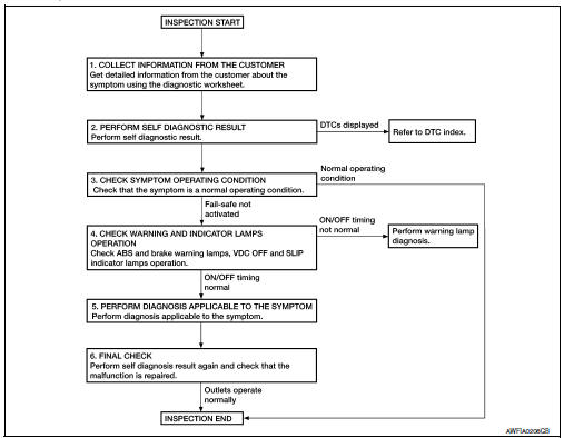
DETAILED FLOW
1.COLLECT INFORMATION FROM THE CUSTOMER
Get detailed information from the customer about the symptom (the condition and the environment when the incident/malfunction occurred) using the diagnostic worksheet. Refer to BRC-52, "Diagnostic Work Sheet".
>> GO TO 2.
2.PERFORM SELF DIAGNOSTIC RESULT
Perform self diagnostic result. Refer to BRC-31, "CONSULT Function (ABS)".
Are any DTCs displayed? YES >> Refer to BRC-43, "DTC Index".
NO >> GO TO 3.
3.CHECK SYMPTOM OPERATING CONDITION
Check that the symptom is a normal operating condition. Refer to BRC-105, "Description".
Is the symptom a normal operating condition? YES >> Inspection End.
NO >> GO TO 4.
4.CHECK WARNING AND INDICATOR LAMPS OPERATION
Check ABS and brake warning lamps, and VDC OFF and SLIP indicator lamps operation. Refer to MWI-8, "METER SYSTEM : System Description".
Is ON/OFF timing normal? YES >> GO TO 5.
NO >> Perform warning lamp diagnosis. Refer to BRC-94, "Component Function Check" (ABS warning lamp), BRC-95, "Component Function Check" (brake warning lamp), BRC-96, "Component Function Check" (VDC OFF indicator lamp) or BRC-97, "Component Function Check" (SLIP indicator lamp).
5.PERFORM DIAGNOSIS APPLICABLE TO THE SYMPTOM
Perform diagnosis applicable to the symptom. Refer to BRC-98, "Symptom Table".
>> GO TO 6.
6.FINAL CHECK
Perform self diagnostic result again, and check that the malfunction is repaired. After checking, erase the self diagnosis memory. Refer to BRC-31, "CONSULT Function (ABS)".
>> Inspection End
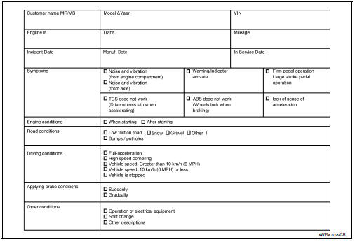
Diagnostic Work Sheet
Additional service when replacing abs actuator and electric unit (control unit)
Description
When replacing the ABS actuator and electric unit (control unit), perform steering angle sensor neutral position adjustment. Refer to BRC-54, "Work Procedure".
 Basic inspection
...
 Adjustment of steering angle sensor neutral position
Description
Refer to the table below to determine if adjustment of steering
angle sensor neutral position is required.
×: Required –: Not required
Work Procedure
ADJUSTMENT OF ST ...
Other materials:
Body side trim
Exploded View
Rear body side welt
Front body side welt
Tether clip
Front pillar finisher
Metal clip
Dash clip
Dash side finisher
Harness protector
Front kicking plate inner
Center pillar lower finisher
Rear kicking plate inner
Cap
Center pillar upper finisher
Rear p ...
Component parts
Component parts location
BCM (view with instrument panel removed)
Key switch
(without Intelligent Key)
Push-button ignition switch
(with Intelligent Key)
IPDM E/R
Illumination control switch
Combination switch (lighting and
turn signal switch)
Front door lock LH (key cylin ...
Can communication circuit
Diagnosis procedure
1.Connector inspection
Turn the ignition switch off.
Disconnect the battery cable from the negative terminal.
Disconnect all the unit connectors on CAN communication system.
Check terminals and connectors for damage, bend and loose connection.
Is the inspection resu ...
