Nissan Sentra B18 (2020-2025) Service Manual: Diagnosis and Repair Work Flow
Work Flow
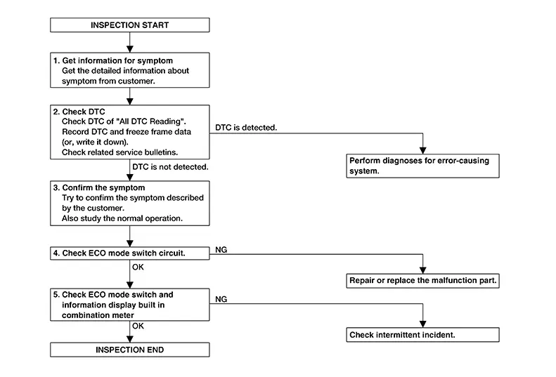
OVERALL SEQUENCE
DETAILED FLOW
-
GET INFORMATION FOR SYMPTOM
Get the detailed information from the customer about the symptom (the condition and the environment when the incident/malfunction occurred) using the ŌĆ£Diagnostic Work SheetŌĆØ. (Refer to Diagnostic Work Sheet)
>>GO TO 2.
-
CHECK DTC
 CONSULT
-
Check DTC of ŌĆ£All DTC ReadingŌĆØ.
-
Perform the following procedure if DTC is displayed.
-
Record DTC and freeze frame data. (Or, write it down.)
-
-
Check related service bulletins for information.
Is any DTCs detected?
YES >>Perform the trouble diagnosis for DTC indicated.
NO >>GO TO 3.
-
-
CONFIRM THE SYMPTOM
Try to confirm the symptom described by the customer.
Also study the normal operation related to the system. Refer to System Description.
>>GO TO 4.
-
CHECK ECO MODE SWITCH CIRCUIT
Check ECO mode switch circuit. Refer to Diagnosis Procedure.
Is inspection result normal?
YES >>GO TO 5.
NO >>Repair or replace malfunctioning component.
-
CHECK ECO MODE SWITCH AND METER INDICATION
-
Ignition switch OFF and wait at least 10 seconds.
-
Ignition switch ON.
-
Check that STANDARD is displayed on the information display screen of the combination meter.
-
Check that the view of information display changes as ECO mode indicator signal (OFF).
-
Check that the view of information display changes as ECO mode indicator signal (ON).
Is the inspection result normal?
YES >>Inspection End.
NO >>Check intermittent incident. Refer to Intermittent Incident.
-
 Basic Inspection
...

Other materials:
Structure and Operation
Positive Crankcase Ventilation
Structure and Operation
Structure and Operation
This system returns blow-by gas to the intake manifold.The
positive crankcase ventilation (PCV) valve is provided to conduct crankcase
blow-by gas to the intakemanifold.
During partial throttle ope ...
Vacuum Pump
Exploded View
Exploded View
1.
Vacuum tube
2.
Clamp
3.
Vacuum hose A ...
P2127 App Sensor
Dtc Description
DTC Description
DTC DETECTION LOGIC
DTC
CONSULT screen terms
(Trouble diagnosis
content)
DTC detection
condition
...
