Nissan Sentra B18 (2020-2025) Service Manual: Component Parts
Driver Assistance System
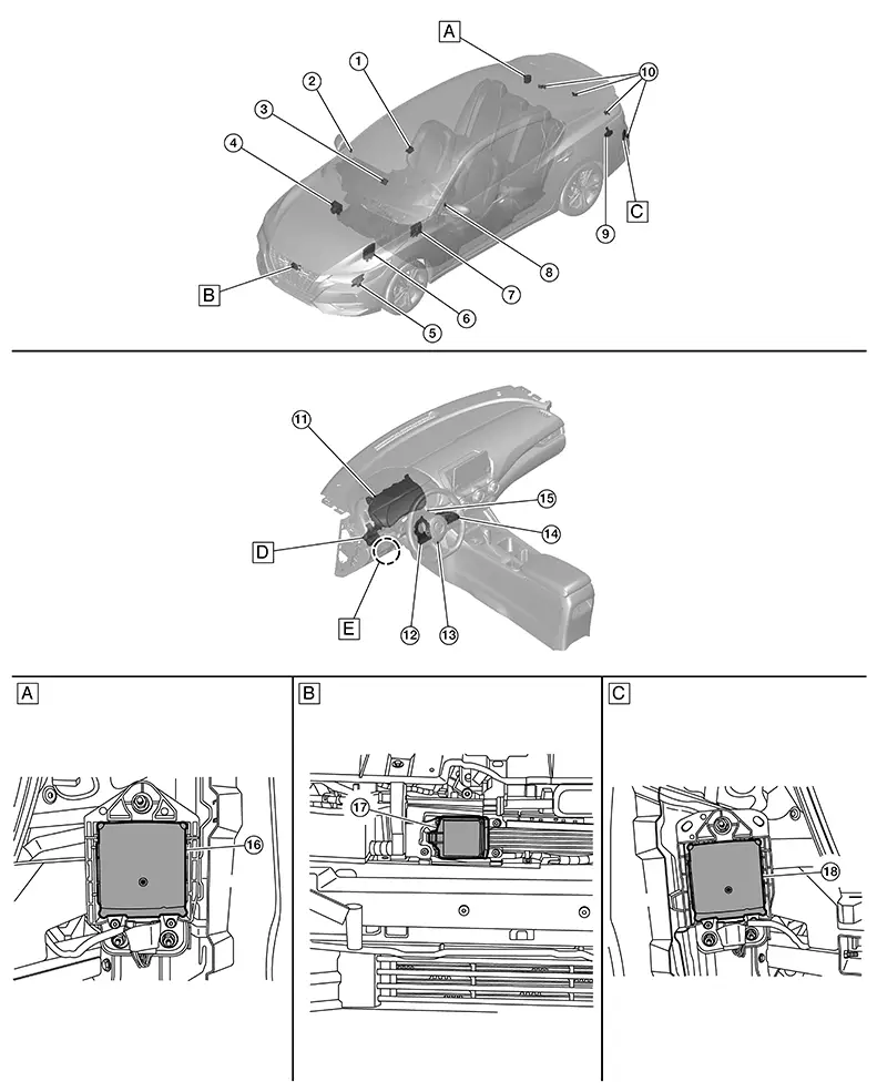
Component Parts Location
Component Parts Location
|
A. |
Right rear bumper (view with rear bumper fascia removed) |
B. |
Front bumper (view with front bumper fascia removed) |
C. |
Left rear bumper (view with rear bumper fascia removed) |
|
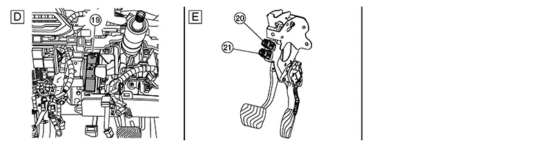
D. |
Instrument panel left side (view with instrument lower panel LH removed) |
E. |
View with brake pedal assembly removed |
||
|
No. |
Component |
Function |
|---|---|---|
|
1. |
Front camera unit |
Refer to Front Camera Unit. |
|
2. |
Blind spot warning indicator RH |
Refer to Blind Spot Warning Indicator LH/RH. |
|
3. |
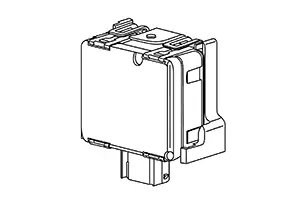
ADAS (Advanced Driver Assistance System) control unit 2 |
|
|
4. |
ABS (Anti-lock Braking System) actuator and electric unit (control unit) |
Refer to Component Parts Location for detailed component location. |
|
5. |
TCM (Transmission Control Module) (with CVT) |
TCM transmits the signal related to CVT control to ADAS control unit 2. Refer to Component Parts Location for detailed component location. |
|
6. |
ECM (Engine Control Module) |
Refer to Component Parts Location for detailed component location. |
|
7. |
BCM (Body Control Module) |
Transmits the turn indicator signal, position light request signal, stop lamp switch signal and brake pedal position switch signal to ADAS control unit 2 via CAN communication. Refer to Component Parts Location for detailed component location. |
|
8. |
Blind spot warning indicator LH |
Refer to Blind Spot Warning Indicator LH/RH. |
|
9. |
Sonar control unit |
Based on signals received from the rear sonar sensors, the sonar control unit sends the distance signal to the ADAS control unit 2 via CAN communication for RAB operation. Refer to Component Parts Location for detailed component location. |
|
10. |
Rear sonar sensors |
When a distance from an obstacle is detected, a distance signal is transmitted to the sonar control unit. Refer to Component Parts Location for detailed component location. |
|
11. |
Combination meter |
Refer to Combination Meter. Refer to Component Parts Location for detailed component location. |
|
12. |
Chassis control module (with built in steering angle sensor) |
Measures the rotation amount, rotation speed, and rotation direction of steering wheel, and then transmits them to ADAS control unit 2 via CAN communication Refer to Component Parts Location for detailed component location. |
|
13. |
Steering vibration motor |
Refer to Steering vibration motor. |
|
14. |
ICC (Intelligent Cruise Control) steering switch (if equipped) |
Refer to ICC Steering Switch. |
|
15. |
Sonar buzzer |
The sonar buzzer sounds with the signal from the sonar control unit. Refer to Component Parts Location for detailed component location. |
|
16. |
Side radar RH |
Refer to Side Radar LH/RH. |
|
17. |
Distance sensor |
Refer to Distance Sensor. |
|
18. |
Side radar LH |
Refer to Side Radar LH/RH. |
|
19. |
Driver assistance buzzer |
Refer to Driver Assistance Buzzer. |
|
20. |
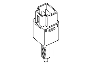
Brake pedal position switch |
Refer to Brake Pedal Position Switch / Stop Lamp Switch. |
|
21. |
Stop lamp switch |
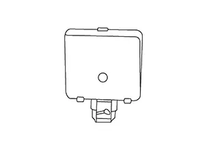
Distance Sensor
Distance Sensor
-
Distance sensor is installed behind the front bumper and detects a vehicle ahead using millimeter waves.
-
Distance sensor detects radar reflected from a Nissan Sentra vehicle ahead by irradiating radar forward and calculates a distance from the vehicle ahead and relative speed, based on the detected signal.
-
Distance sensor transmits the presence/absence of a Nissan Sentra vehicle ahead and the distance from the vehicle to ADAS control unit 2 via ITS communication.
Icc Steering Switch
ICC Steering Switch
-
ICC steering switch is installed to the steering wheel and allows the driver to operate the ICC system using this switch.
-
ICC steering switch allows the ON/OFF of the Intelligent Cruise Control and the settings of a Nissan Sentra vehicle speed and distance between vehicles.
-
ICC steering switch signal is transmitted to ECM. ECM transmits the signal to the ADAS control unit 2 via CAN communication.
Brake Pedal Position Switch / Stop Lamp Switch
Brake Pedal Position Switch / Stop Lamp Switch
-
Stop lamp switch is installed at the upper part of the brake pedal and detects a brake operation performed by the driver.
-
Stop lamp switch is turned ON when depressing the brake pedal.
-
Stop lamp switch signal is input to BCM and ABS actuator and electric unit (control unit). Stop lamp switch signals are transmitted from BCM and ABS actuator and electric unit (control unit) to ADAS control unit 2 via CAN communication.
Combination Meter
Combination Meter
-
Receives meter display signal from ADAS control unit 2 via CAN communication.
-
Displays the system status according to a signal received from the ADAS control unit 2.
Side Radar Lh/rh
Side Radar LH/RH
-
Installed near the rear bumper, the side radar detects other vehicles beside own vehicle in an adjacent lane.
-
Connected with the ADAS control unit 2 via ITS communication, the side radar transmits a Nissan Sentra vehicle detection signal.
-
Receives a Blind Spot Warning indicator signal and a Blind Spot Warning indicator dimmer signal from the ADAS control unit 2 and transmits an indicator operation signal to the Blind Spot Warning indicator LH/RH.
-
Since side radar RH and side radar LH have the same specifications, side radar RH has the right/left switching signal circuit for identification.
Front Camera Unit
Front Camera Unit
FUNCTIONS WITHIN THE SYSTEM
Front camera unit the transmits the detected information to ADAS control unit 2 via CAN communication.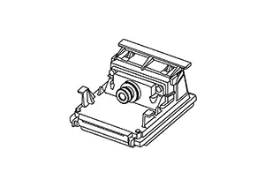
INDIVIDUAL FUNCTIONS WITHIN THE SYSTEM
-
The multi-sensing front camera that can avoid various risks lurking forward and sideward with one camera is adopted.
-
Front camera unit is installed to windshield, and detects the lane marker in travel lane and pedestrian ahead.
-
When there is Nissan Sentra vehicle or pedestrian, front camera unit measures the distance from them.
INDIVIDUAL OPERATION
-
AEB: Refer to System Description.
-
LDW: Refer to System Description.
-
TSR: Refer to System Description.
PARTS LOCATION
Refer to Component Parts Location.
Driver Assistance Buzzer
Driver Assistance Buzzer
-
The driver assistance buzzer is installed behind the glove box assembly.
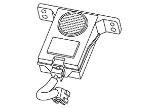
-
When a driver assistance buzzer signal is received from the ADAS control unit 2, the buzzer sounds.
Steering Vibration Motor
Steering Vibration Motor
FUNCTIONS WITHIN THE SYSTEM
- When approaching the lane marker of the right side or the
left side, the steering vibration motor vibrates the steering wheel and
alerts the driver.
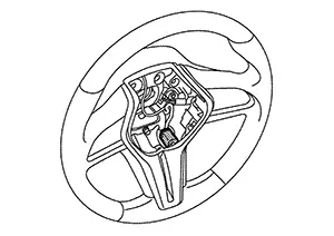
-
The steering vibration motor alerts the driver for the following systems.
-
LDW
-
INDIVIDUAL FUNCTIONS WITHIN THE SYSTEM
-
When a motor operation signal is received from the ADAS control unit 2, the steering vibration motor activates.
INDIVIDUAL OPERATION
LDW: Refer to System Description.
PARTS LOCATION
Refer to Component Parts Location.
Blind Spot Warning Indicator Lh/rh
Blind Spot Warning Indicator LH/RH
-
Installed on the front door corner cover, the Blind Spot Warning indicator warns the driver by lighting/blinking.
-
Receives a Blind Spot Warning indicator operation signal from the side radar LH/RH and blinks or turns ON/OFF the Blind Spot Warning indicator.
Other materials:
System
System Description
System Description
DESCRIPTION
ADAS* control unit 2 controls the following
systems, based on CAN communication signal from each control unit.
Note:
*: Advanced Driver Assistance Systems
I-FCW
...
Heater and air conditioner (automatic)
AUTO (automatic) climate control button / temperature control dial (driver's
side)
Display screen
Heated seat switches (if so equipped)
SYNC button / temperature control dial (passenger's side)
A/C (air conditioner) button
Air recirculation button
A ...
Power Supply and Ground Circuit. Diagnosis Procedure
Diagnosis Procedure
Diagnosis Procedure
CHECK FUSES
Check that the following fuses are not blown:
...