Nissan Sentra B18 (2020-2025) Service Manual: Component Parts
Meter System
Component Parts Location
Component Parts Location
MODELS WITH CVT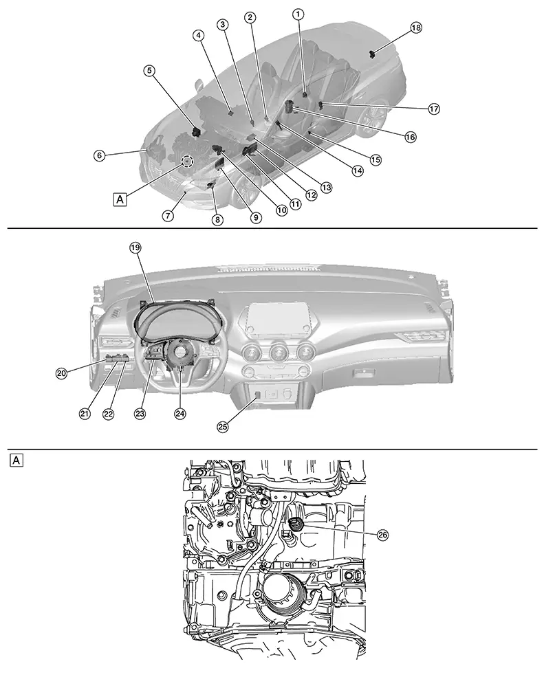
|
A. |
View of engine assembly removed |
|
No. |
Component |
Function |
|---|---|---|
|
1. |
Rear seat belt buckle switch RH & CTR |
Transmits the rear seat belt buckle switch RH & CTR signal to the air bag diagnosis sensor unit. |
|
2. |
Front seat belt buckle switch RH |
Transmits the front seat belt buckle switch RH signal to the air bag diagnosis sensor unit. |
|
3. |
CVT selector (drive sport mode switch) (if so equipped) |
Transmits the drive sport mode switch signal to the BCM. |
|
4. |
ADAS (Advanced Driver Assistance System) control unit 2 |
Transmits each signal to the combination meter via CAN communication. Refer to System Description. Refer to Component Parts Location for detailed component location. |
|
5. |
ABS (Anti-lock Braking System) actuator and electric unit (control unit) |
Transmits each signal to the combination meter via CAN communication. Refer to System Description. Refer to Component Parts Location for detailed component location. |
|
6. |
Washer fluid level switch (if so equipped) |
Transmits the washer fluid level switch signal to the combination meter. Refer to Component Parts Location for detailed component location. |
|
7. |
Ambient sensor |
Transmits the ambient sensor signal to the combination meter. |
|
8. |
TCM (Transmission Control Module) |
Transmits each signal to the combination meter via CAN communication. Refer to System Description. Refer to Component Parts Location for detailed component location. |
|
9. |
ECM (Engine Control Module) |
Transmits each signal to the combination meter via CAN communication. Refer to System Description. Refer to Component Parts Location for detailed component location. |
|
10. |
Brake fluid level switch |
Transmits the brake fluid level switch signal to the combination meter. Refer to Component Parts Location for detailed component location. |
|
11. |
Parking brake switch |
Transmits the parking brake switch signal to the combination meter. |
|
12. |
BCM (Body Control Module) |
Transmits each signal to the combination meter via CAN communication. Refer to System Description. Refer to Component Parts Location for detailed component location. |
|
13. |
Air bag diagnosis sensor unit |
Transmits each signal to the combination meter via CAN communication. Refer to System Description. Refer to Component Parts Location for detailed component location. |
|
14. |
Front seat belt buckle switch LH |
Transmits the front seat belt buckle switch LH signal to the BCM. |
|
15. |
Front door switch LH |
Transmits the front door switch LH signal to the BCM. |
|
16. |
Fuel level sensor unit and fuel pump (fuel level sensor) |
Transmits the fuel level sensor signal to the combination meter. |
|
17. |
Rear seat belt buckle switch LH |
Transmits the rear seat belt buckle switch LH signal to the air bag diagnosis sensor unit. |
|
18. |
Trunk lid opener assembly (ajar switch) |
Transmits the trunk lid opener assembly (ajar switch) signal to the BCM. |
|
19. |
Combination meter |
Refer to Combination Meter. |
|
20. |
ECO mode switch |
Transmits the ECO mode switch signal to the BCM. |
|
21. |
Illumination control switch |
Refer to Illumination Control Switch. |
|
22. |
Trip reset switch |
Refer to Trip Reset Switch. |
|
23. |
Steering switches |
Refer to Steering Switches. |
|
24. |
Combination switch (spiral cable) |
Provides a pass-through for the steering switch signal from the steering switches to the combination meter. |
|
25. |
Start/stop OFF switch (if so equipped) |
Transmits the start/stop OFF switch signal to the BCM. |
|
26. |
Engine oil pressure sensor |
Transmits the engine oil pressure sensor signal to the ECM. |

|
A. |
View of engine assembly removed |
B. |
Left side of instrument panel |
|
No. |
Component |
Function |
|---|---|---|
|
1. |
Rear seat belt buckle switch RH & CTR |
Transmits the rear seat belt buckle switch RH & CTR signal to the air bag diagnosis sensor unit. |
|
2. |
Front seat belt buckle switch RH |
Transmits the front seat belt buckle switch RH signal to the air bag diagnosis sensor unit. |
|
3. |
ADAS (Advanced Driver Assistance System) control unit 2 |
Transmits each signal to the combination meter via CAN communication. Refer to System Description. Refer to Component Parts Location for detailed component location. |
|
4. |
ABS (Anti-lock Braking System) actuator and electric unit (control unit) |
Transmits each signal to the combination meter via CAN communication. Refer to System Description. Refer to Component Parts Location for detailed component location. |
|
5. |
Washer fluid level switch (if so equipped) |
Transmits the washer fluid level switch signal to the combination meter. Refer to Component Parts Location for detailed component location. |
|
6. |
Ambient sensor |
Transmits the ambient sensor signal to the combination meter. |
|
7. |
ECM (Engine Control Module) |
Transmits each signal to the combination meter via CAN communication. Refer to System Description. Refer to Component Parts Location for detailed component location. |
|
8. |
Brake fluid level switch |
Transmits the brake fluid level switch signal to the combination meter. Refer to Component Parts Location for detailed component location. |
|
9. |
BCM (Body Control Module) |
Transmits each signal to the combination meter via CAN communication. Refer to System Description. Refer to Component Parts Location for detailed component location. |
|
10. |
Air bag diagnosis sensor unit |
Transmits each signal to the combination meter via CAN communication. Refer to System Description. Refer to Component Parts Location for detailed component location. |
|
11. |
Parking brake switch |
Transmits the parking brake switch signal to the combination meter. |
|
12. |
Front seat belt buckle switch LH |
Transmits the front seat belt buckle switch LH signal to the BCM. |
|
13. |
Front door switch LH |
Transmits the front door switch LH signal to the BCM. |
|
14. |
Fuel level sensor unit and fuel pump (fuel level sensor) |
Transmits the fuel level sensor signal to the combination meter. |
|
15. |
Rear seat belt buckle switch LH |
Transmits the rear seat belt buckle switch LH signal to the air bag diagnosis sensor unit. |
|
16. |
Trunk lid opener assembly (ajar switch) |
Transmits the trunk lid opener assembly (ajar switch) signal to the BCM. |
|
17. |
Combination meter |
Refer to Combination Meter. |
|
18. |
ECO mode switch |
Transmits the ECO mode switch signal to the BCM. |
|
19. |
Illumination control switch |
Refer to Illumination Control Switch. |
|
20. |
Trip reset switch |
Refer to Trip Reset Switch. |
|
21. |
Steering switches |
Refer to Steering Switches. |
|
23. |
Engine oil pressure sensor |
Transmits the engine oil pressure sensor signal to the ECM. |
|
24. |
Combination switch (spiral cable) |
Provides a pass-through for the steering switch signal from the steering switches to the combination meter. |
Design
Design
ARRANGEMENT OF COMBINATION METER
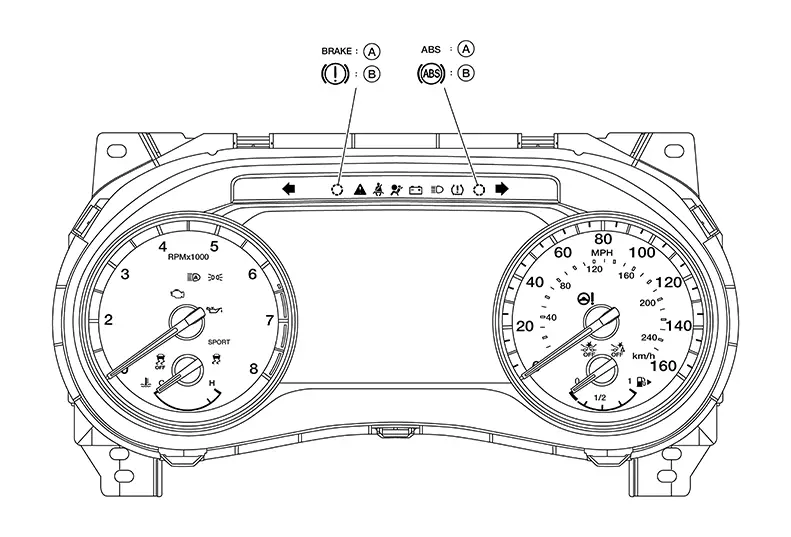
|
A. |
USA |
B. |
Except USA |
Combination Meter
Combination Meter
The combination meter controls the following items according to the signals received from each unit via CAN communication and the signals from switches and sensors:
-
Measuring instruments
-
Indicator lamps
-
Warning lamps
-
Meter illumination control
-
Information display
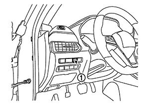
Trip Reset Switch
Trip Reset Switch
-
The trip reset switch is located on the instrument panel lower LH.
-
Transmits the trip reset signal to the combination meter.
|
No. |
Switch name |
Operation |
Description |
|---|---|---|---|
|
1. |
Trip reset switch |
Press |
|
Illumination Control Switch
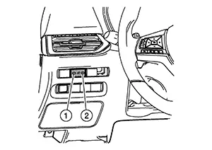
Illumination Control Switch
-
The illumination control switch is located on the instrument lower panel LH.
-
Transmits the following signals to the combination meter:
-
Illumination control switch signal (+)
-
Illumination control switch signal (−)
-
|
No. |
Switch name |
Operation |
Description |
|---|---|---|---|
|
1. |
Illumination control switch (−) |
Press |
The brightness of combination meter and information display can be adjusted. |
|
2. |
Illumination control switch (+) |
Steering Switches
Steering Switches
-
The steering switches are located on the steering wheel.
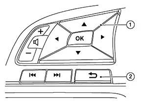
-
The steering switch transmits the steering switch signal to the combination meter.
|
No. |
Switch name |
Operation |
Description |
|---|---|---|---|
|
1. |
OK/Up/Down/Left/Right switch |
Press |
The information display settings can be changed. |
|
2. |
Back switch |
Other materials:
P27b5-00 Control Module
Dtc Description
DTC Description
DTC DETECTION LOGIC
DTC
CONSULT screen terms
(Trouble diagnosis
content)
DTC detection
conditi ...
P0719 Brake Pedal Switch B
Dtc Description
DTC Description
DTC DETECTION LOGIC
DTC
CONSULT screen terms
(Trouble diagnosis
content)
DTC detection
condition
...
B20ce-15 Hl (hi) Lh Pwr Sply Circ
Dtc Description
DTC Description
DTC DETECTION LOGIC
DTC No.
CONSULT screen items
(Trouble diagnosis content)
DTC detection condition
...