Nissan Sentra B18 (2020-2025) Service Manual: Component Parts
Engine Control System
Component Parts Location
Component Parts Location
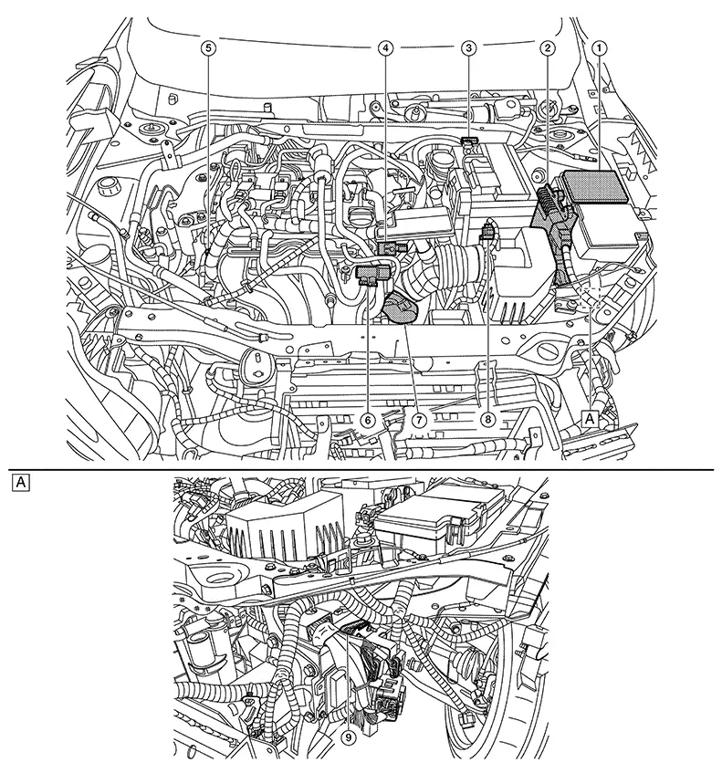
ENGINE ROOM COMPARTMENT
|
|
Area behind left head lamp |

|
No. |
Component |
Function |
|---|---|---|
|
|
IPDM E/R |
IPDM E/R control the internal relays and the actuators. And when CAN communication with ECM is impossible, IPDM E/R performs fail-safe control.
|
|
|
ECM |
Component Description |
|
|
Battery current sensor |
Component Description |
|
|
Intake manifold runner control valve motor |
Component Description. |
|
|
Intake manifold runner control valve position sensor |
Component Description |
|
|
EVAP canister purge volume control solenoid valve |
Component Description |
|
|
Electric throttle control actuator (with built in throttle position sensor and throttle control motor) |
Component Description |
|
|
Mass air flow sensor (with intake air temperature sensor) |
Component Description |
|
|
Electric intake valve timing control module |
Component Description |


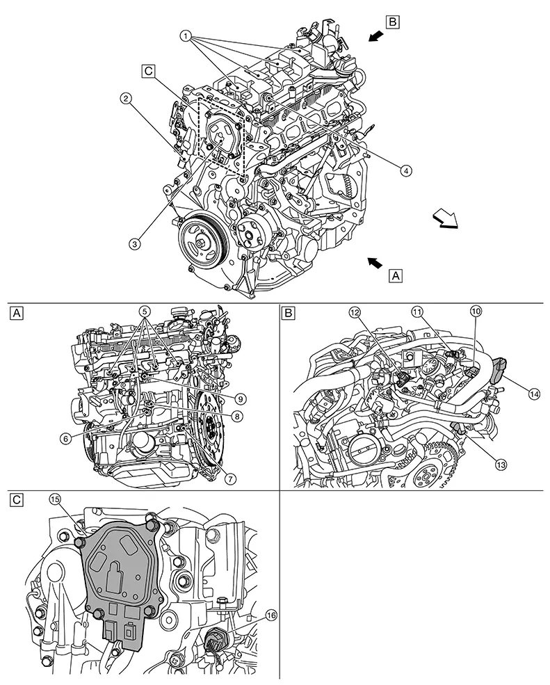
ENIGNE COMPARTMENT
|
|
Nissan Sentra Vehicle front side |
|
Nissan Sentra Vehicle left side |
|
Nissan Sentra Vehicle right side |
|
|
Nissan Sentra Vehicle front |


|
No. |
Component |
Function |
|---|---|---|
|
|
Ignition coil |
Component Description |
|
|
Exhaust valve timing control solenoid valve |
Component Description |
|
|
Electric intake valve timing control actuator |
Component Description |
|
|
PCV valve |
Structure and Operation |
|
|
Fuel injector |
Component Description |
|
|
Engine oil temperature sensor |
Component Description |
|
|
Crankshaft position sensor |
Component Description |
|
|
Engine oil pressure sensor |
Component Description |
|
|
Knock sensor |
Component Description |
|
|
Exhaust camshaft position sensor |
Component Description |
|
|
High pressure fuel pump |
Component Description |
|
|
Intake camshaft position sensor |
Component Description |
|
|
Engine coolant temperature sensor |
Component Description |
|
|
EGR volume control valve |
Component Description |
|
|
Electric intake valve timing control motor |
Component Description |
|
|
Fuel rail pressure sensor |
Component Description |


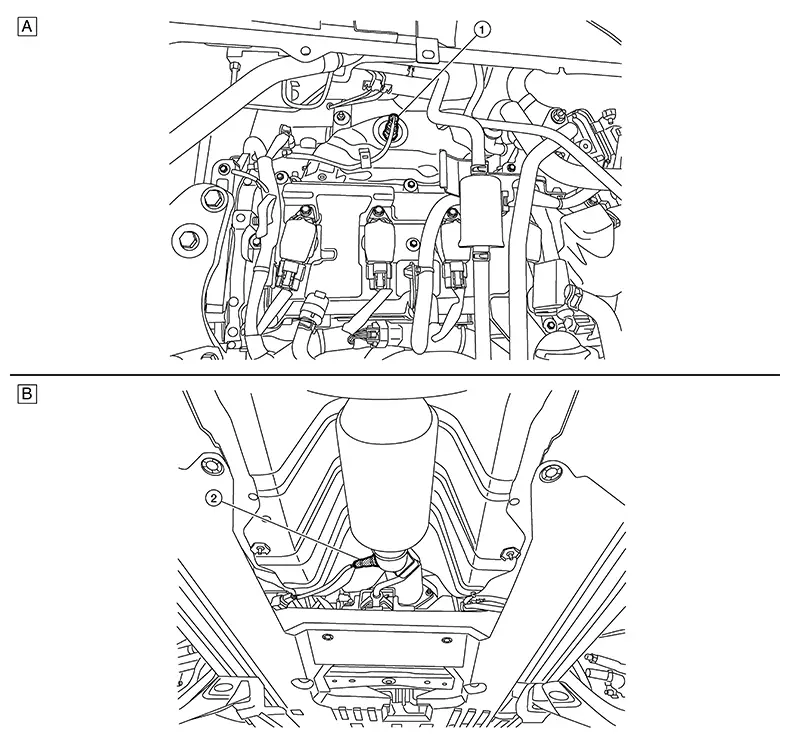
EXHAUST COMPARTMENT
|
|
Rear of engine compartment |
|
Underbody |
|
No. |
Component |
Function |
|---|---|---|
|
|
Air fuel ratio (A/F) sensor 1 |
Component Description |
|
|
Heated oxygen sensor 2 |
Component Description |
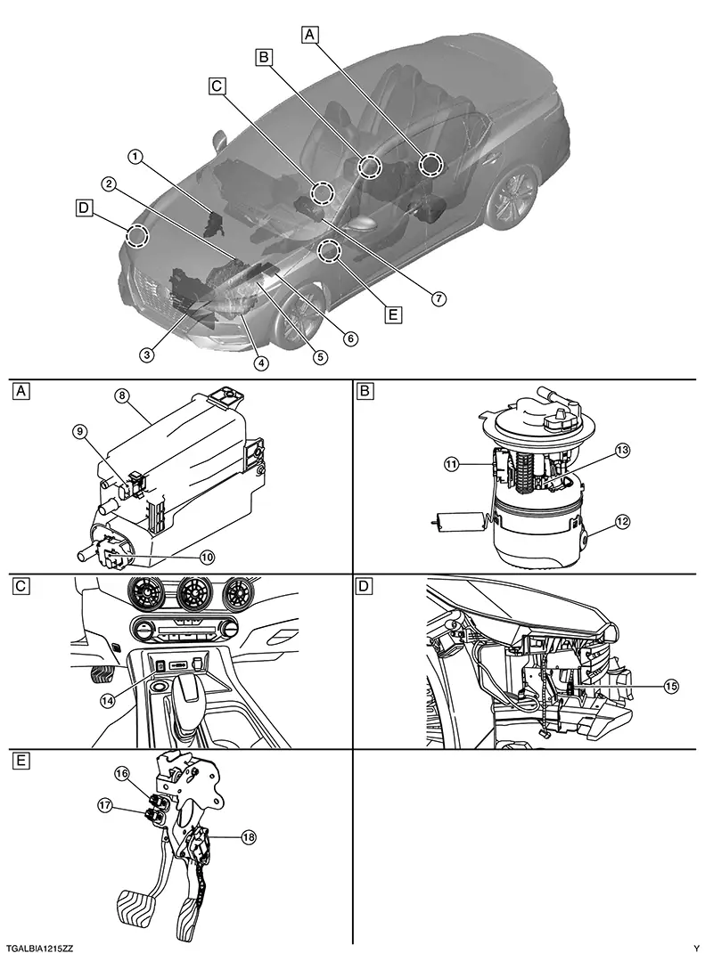
BODY COMPARTMENT
|
|
Under carriage area behind fuel tank |
|
Inside fuel tank periphery |
|
Front center of instrument panel |
|
|
Right front engine compartment |
|
Pedal periphery area |


|
No. |
Component |
Function |
|
|---|---|---|---|
|
|
ABS actuator and electric unit (CONTROL UNIT) |
ABS Actuator and Electric Unit (Control Unit) | |
|
|
EPS control unit |
EPS Control Unit |
|
|
|
Cooling fan motor |
Component Description |
|
|
|
ECM |
Component Description |
|
|
|
IPDM E/R |
IPDM E/R control the internal relays and the actuators. And when CAN communication with ECM is impossible, IPDM E/R performs fail-safe control.
|
|
|
|
Combination meter |
Malfunction indicator lamp (MIL) |
Warning/Indicator (On Information Display) |
|
Information display |
Warning/Indicator (On Information Display) |
||
|
|
EVAP canister |
Component Description |
|
|
|
EVAP control system pressure sensor |
Component Description |
|
|
|
EVAP canister vent control valve |
Component Description |
|
|
|
Fuel level sensor |
Component Description |
|
|
|
Fuel tank temperature sensor |
Component Description |
|
|
|
Fuel pump |
Component Description |
|
|
|
Start/Stop off switch |
Component Description |
|
|
|
Refrigerant pressure sensor |
Component Description |
|
|
|
Brake pedal position switch |
Component Description |
|
|
|
Stop lamp switch |
Stop Lamp Switch |
|
|
|
Accelerator pedal position sensor |
Component Description |
|

Accelerator Pedal Position Sensor
Component Description
Component Description
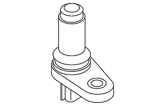
The accelerator pedal position sensor is installed on the upper end of the accelerator pedal assembly. The sensor detects the accelerator position and sends a signal to the ECM.
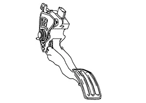
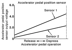
Accelerator pedal position sensor has two sensors. These sensors are a kind of potentiometers which transform the accelerator pedal position into output voltage, and emit the voltage signal to the ECM. In addition, these sensors detect the opening and closing speed of the accelerator pedal and feed the voltage signals to the ECM. The ECM judges the current opening angle of the accelerator pedal from these signals and controls the throttle control motor based on these signals.
Idle position of the accelerator pedal is determined by the ECM receiving the signal from the accelerator pedal position sensor. The ECM uses this signal for the engine operation such as fuel cut.
Ascd Steering Switch
Component Description
Component Description
ASCD steering switch has variant values of electrical resistance for each button. ECM reads voltage variation of switch, and determines which button is operated.
Cooling Fan
Component Description
Component Description
Cooling fan operates at each speed when the current flows in the cooling fan motor as follows. Refer to System Description. System Description" for cooling fan operation.
Clutch Pedal Position Switch
Component Description
Component Description
Clutch pedal position switch is installed to clutch pedal bracket. The switch detects the state of the clutch pedal and transmits an ON/OFF signal to ECM.
|
Clutch pedal |
Clutch pedal position switch |
|---|---|
|
Released |
OFF |
|
Depressed |
ON |
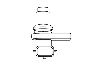
Crankshaft Position Sensor
Component Description
Component Description
The crankshaft position sensor (POS) is located on the Cylinder block rear end. It detects the fluctuation of the engine revolution.
The sensor consists of a permanent magnet and Hall IC. When the engine is running, the high and low parts of the teeth cause the gap with the sensor to change. The changing gap causes the magnetic field near the sensor to change. Due to the changing magnetic field, the voltage from the sensor changes. The ECM receives the voltage signal and detects the fluctuation of the engine revolution.
Ecm
Component Description
Component Description
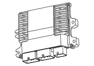
The ECM consists of a microcomputer and connectors for signal input and output and for power supply. The ECM controls the engine.The atmospheric pressure sensor is built into ECM.
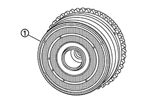
Electric Intake Valve Timing Control Actuator
Component Description
Component Description
FUNCTIONS WITHIN THE SYSTEM
The electric intake valve timing control actuator operates the electric intake valve timing control motor based on the signal from the electric intake valve timing control module, and it advances or retards the intake valve timing according to the conditions. It also transmits the motor position and motor speed to the electric intake valve timing control module based on the electric intake valve timing control position sensor.
INDIVIDUAL FUNCTION WITHIN THE SYSTEM
It is composed of the electric intake valve timing control motor and electric intake valve timing control actuator (located inside the electric intake valve timing control position sensor).
INDIVIDUAL OPERATION
The electric intake valve timing control motor rotates in the same direction as the intake camshaft, and the difference in rotation controls timing advancement, holding, and retardation.
COMPONENT PARTS LOCATION
The electric intake valve timing control actuator (located inside the electric intake valve timing control position sensor) is installed on the engine front side of the intake camshaft.
The electric intake valve timing control motor is installed inside
the cam sprocket (INT)  .
.
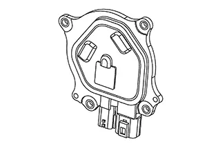
Electric Intake Valve Timing Control Module
Component Description
Component Description
FUNCTIONS WITHIN THE SYSTEM
The electric intake valve timing control module controls the electric intake valve timing control actuator based on the signals from the ECM and the electric intake valve timing control position sensor. The target intake valve timing angle is also corrected by the signal transmitted from the ECM via CAN communication.
INDIVIDUAL FUNCTION WITHIN THE SYSTEM
The electric intake valve timing control module controls the electric intake valve timing control actuator according to the signal from the ECM, and changes the intake valve open/close timing. It also has a diagnosis function and transmits a malfunction detection signal to the ECM via CAN communication.
INDIVIDUAL OPERATION
The electric intake valve timing control module controls the electric intake valve timing control actuator, and if it detects a malfunction, it transmits a malfunction detection signal to the ECM via CAN communication.
COMPONENT PARTS LOCATION
The electric intake valve timing control module is installed to the engine room left side.
Electric Throttle Control Actuator
Component Description
Component Description
Description
Electric throttle control actuator consists of throttle body, throttle valve, throttle control motor and throttle position sensor.
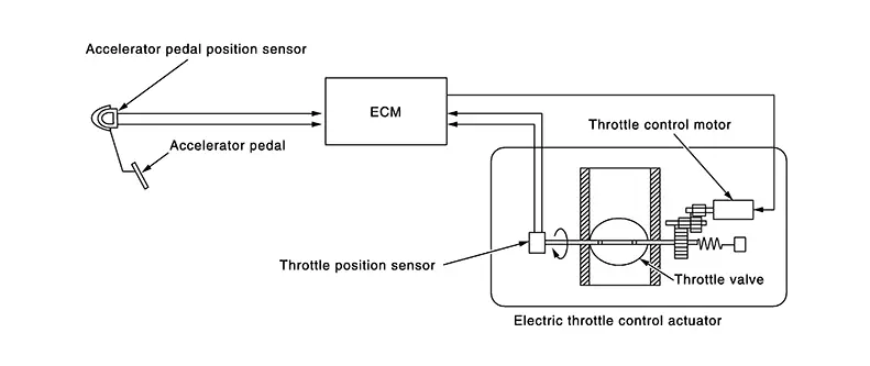
THROTTLE CONTROL MOTOR RELAY
Power supply for the throttle control motor is provided to the ECM via throttle control motor relay. The throttle control motor relay is ON/OFF controlled by the ECM. When the ignition switch is turned ON, the ECM sends an ON signal to throttle control motor relay and battery voltage is provided to the ECM. When the ignition switch is turned OFF, the ECM sends an OFF signal to throttle control motor relay and battery voltage is not provided to the ECM.
THROTTLE CONTROL MOTOR
The throttle control motor is operated by the ECM and it opens and closes the throttle valve.
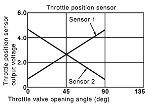
THROTTLE POSITION SENSOR
The throttle position sensor has two sensors. These sensors are a kind of potentiometers which transform the throttle valve position into output voltage, and emit the voltage signal to the ECM. In addition, these sensors detect the opening and closing speed of the throttle valve and feed the voltage signals to the ECM. The ECM judges the current opening angle of the throttle valve from these signals and the ECM controls the throttle control motor to make the throttle valve opening angle properly in response to driving condition.
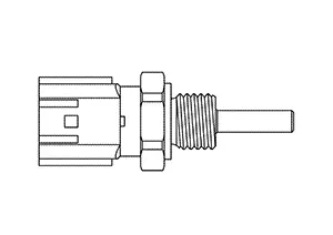
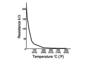
Engine Coolant Temperature Sensor
Component Description
Component Description
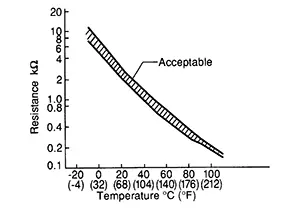
The engine coolant temperature sensor is used to detect the engine coolant temperature. The sensor modifies a voltage signal from the ECM. The modified signal returns to the ECM as the engine coolant temperature input. The sensor uses a thermistor which is sensitive to the change in temperature. The electrical resistance of the thermistor decreases as temperature increases.
<Reference data>
|
Engine coolant temperature [┬░C (┬░F)] |
Voltage* (V) |
Resistance (kŌä”) |
|---|---|---|
|
ŌłÆ10 (14) |
4.4 |
7.0 - 11.4 |
|
20 (68) |
3.5 |
2.37 - 2.63 |
|
50 (122) |
2.2 |
0.68 - 1.00 |
|
90 (194) |
0.9 |
0.236 - 0.260 |
*: These data are reference values and are measured between ECM terminals.
Engine Oil Temperature Sensor
Component Description
Component Description
The engine oil temperature sensor is used to detect the engine oil temperature. The sensor modifies a voltage signal from the ECM. The modified signal returns to the ECM as the engine oil temperature input. The sensor uses a thermistor which is sensitive to the change in temperature. The electrical resistance of the thermistor decreases as temperature increases.
<Reference data>
|
Engine oil temperature [┬░C (┬░F)] |
Voltage* (V) |
Resistance (kŌä”) |
|---|---|---|
|
ŌĆō10 (14) |
4.4 |
7.0 - 11.4 |
|
20 (68) |
3.5 |
2.37 - 2.63 |
|
50 (122) |
2.2 |
0.68 - 1.00 |
|
90 (194) |
0.9 |
0.236 - 0.260 |
|
110 (230) |
0.6 |
0.143 - 0.153 |
*: These data are reference values and are measured between ECM terminals.
Evap Canister
Component Description
Component Description
EVAP canister stores the generated fuel vapors in the sealed fuel tank to activated charcoals of EVAP canister when the engine is not operating or when refueling to the fuel tank. For details, Refer to System Description.
Evap Canister Purge Volume Control Solenoid Valve
Component Description
Component Description
The EVAP canister purge volume control solenoid valve uses a ON/OFF duty to control the flow rate of fuel vapor from the EVAP canister. The EVAP canister purge volume control solenoid valve is moved by ON/OFF pulses from the ECM. The longer the ON pulse, the greater the amount of fuel vapor that will flow through the valve.
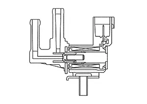
Evap Canister Vent Control Valve
Component Description
Component Description
The EVAP canister vent control valve is located on the EVAP canister and is used to seal the canister vent.
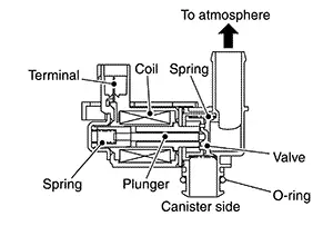
This solenoid valve responds to signals from the ECM. When the ECM sends an ON signal, the coil in the solenoid valve is energized. A plunger will then move to seal the canister vent. The ability to seal the vent is necessary for the on board diagnosis of other evaporative emission control system components.
This solenoid valve is used only for diagnosis, and usually remains opened.
When the vent is closed, under normal purge conditions, the evaporative emission control system is depressurized and allows ŌĆ£EVAP Control SystemŌĆØ diagnosis.
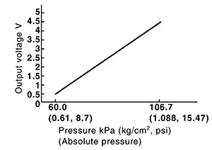
Evap Control System Pressure Sensor
Component Description
Component Description
The EVAP control system pressure sensor detects pressure in the purge line. The sensor output voltage to the ECM increases as pressure increases.
Exhaust Camshaft Position Sensor
Component Description
Component Description
Exhaust camshaft position sensor detects the protrusion of the signal plate installed to the exhaust camshaft rear end.
This sensor signal is used for sensing a position of the exhaust camshaft.
The sensor consists of a permanent magnet and Hall IC.
When engine is running, the high and low parts of the teeth cause the gap with the sensor to change.
The changing gap causes the magnetic field near the sensor to change.
Due to the changing magnetic field, the voltage from the sensor changes.
Exhaust Valve Timing Control Solenoid Valve
Component Description
Component Description
Exhaust valve timing control solenoid valve is activated by ON/OFF pulse duty (ratio) signals from the ECM.
The exhaust valve timing control solenoid valve changes the oil amount and direction of flow through exhaust valve timing control unit or stops oil flow.
The longer pulse width retards valve angle.
The shorter pulse width advances valve angle.
When ON and OFF pulse widths become equal, the solenoid valve stops oil pressure flow to fix the exhaust valve angle at the control position.
Fuel Rail Pressure Sensor
Component Description
Component Description
The fuel rail pressure (FRP) sensor is placed to the fuel rail and
measures fuel pressure in the fuel rail. The sensor transmits voltagesignal to the ECM. As the pressure increases, the voltage rises. The ECM controls the fuel pressure in the fuel rail by operating high pressure fuel pump. The ECM uses the signal from fuel rail pressure sensor as a feedback signal.
Fuel Tank Temperature Sensor
Component Description
Component Description
The fuel tank temperature sensor (FTT sensor) is used
to detect the fuel temperature inside the fuel tank. The sensor modifies a
voltage signal from the ECM. The modified signal returns to the ECM as the fuel
temperature input. The sensor uses a thermistor which is sensitive to the change
in temperature. The electrical resistance of the thermistor decreases as
temperature increases.
<Reference data>
|
Fluid temperature [┬░C (┬░F)] |
Voltage* (V) |
Resistance (kŌä”) |
|---|---|---|
|
20 (68) |
3.5 |
2.3 ŌĆō 2.7 |
|
50 (122) |
2.2 |
0.79 ŌĆō 0.90 |
*: These data are reference values on the diagnosis tool.
Heated Oxygen Sensor 2
Component Description
Component Description
DESCRIPTION
The heated oxygen sensor 2, after three way catalyst (manifold), monitors the oxygen level in the exhaust gas.
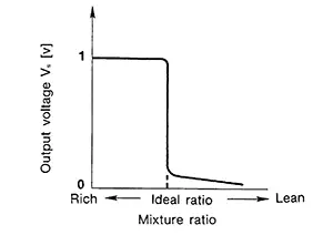
Even if switching characteristics of the air fuel ratio (A/F) sensor 1 are shifted, the air fuel ratio is controlled to stoichiometric, by the signal from the heated oxygen sensor 2.
This sensor is made of ceramic zirconia. The zirconia generates voltage from approximately 1 V in richer conditions to 0 V in leaner conditions.
Under normal conditions the heated oxygen sensor 2 is not used for engine control operation.
HEATED OXYGEN SENSOR 2 HEATER
Heated oxygen sensor 2 heater is integrated in the sensor.
The ECM performs ON/OFF control of the heated oxygen sensor 2 heater corresponding to the engine speed, amount of intake air and engine coolant temperature.
Operation
|
Engine speed |
Heated oxygen sensor 2 heater |
|---|---|
|
Above 3,200 rpm |
OFF |
|
Below 3,200 rpm after the following conditions are met.
|
ON |
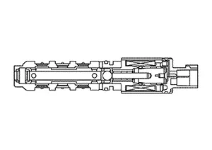
High Pressure Fuel Pump
Component Description
Component Description
-
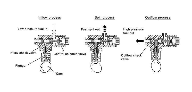
Balanced flow volume control type single cylinder high pressure fuel pump, which approximately equalize the amount of injection and pump output, is adopted.
-
The high pressure fuel pump is activated by the exhaust camshaft. ECM controls the high pressure fuel pump control solenoid valve built into the high pressure fuel pump and adjusts the amount of discharge by changing the suction timing of the low pressure fuel.
-
Inflow process: Cam driven lowering plunger let the fuel from low pressure fuel pump induced into high pressure fuel pump.
-
Spill process: Although the cam driven plunger start moving upward, inflow check valve still at open position due to the control solenoid valve, so the fuel is not pressurized and spilled out to low pressure fuel pump side. By changing the amount of this spill out volume changes the amount of injection.
-
Outflow process: When the control solenoid valve turns ON, the inflow check valve is closed, fuel is pressurized and when the pressure exceeds certain point discharge check valve is pushed open to discharge fuel into fuel rail.
-
 Operating Chart
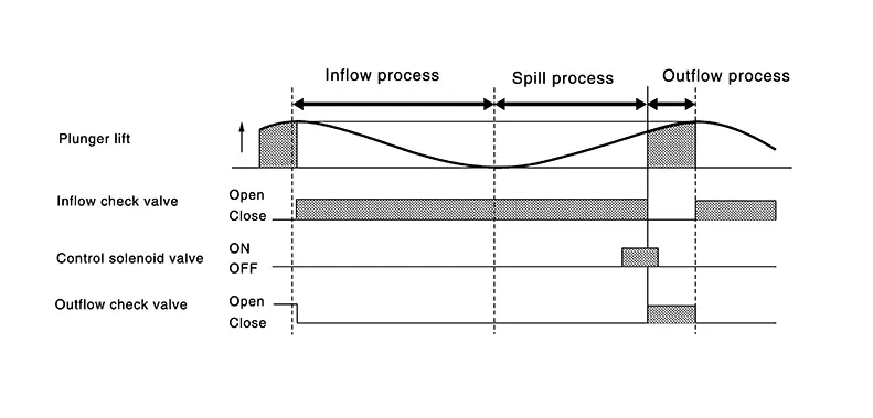
Hood Switch
Component Description
Component Description
FUNCTIONS WITHIN THE SYSTEM
When the ECM receives the hood switch signal via CAN communication, it cancels the idle start/stop system.
INDIVIDUAL FUNCTION WITHIN THE SYSTEM
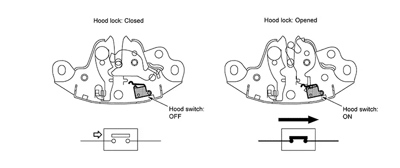
The hood switch detects the hood open/close status and inputs the hood switch signal into the IPDM E/R.
INDIVIDUAL OPERATION
The hood switch turns ON/OFF according to the hood status.
Ignition Coil with Power Transistor
Component Description
Component Description
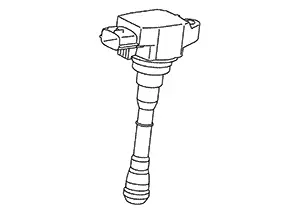
Ignition coil with power transistor
The ignition signal from the ECM is sent to and amplified by the power transistor. The power transistor turns ON and OFF the ignition coil primary circuit. This ON/OFF operation induces the proper high voltage in the coil secondary circuit.
Intake Manifold Runner Control Valve
Component Description
Component Description
Intake manifold runner control valve is consist of intake manifold runner control valve to open/close the right/left half section installed at each port of intake manifold runner control valve motor to drive open/close the valve.
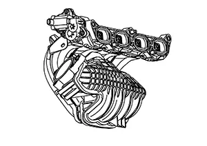
ECM transmits the open/close signal to intake manifold runner control valve motor according to the driving condition based on the signals of engine speed, coolant temperature etc. ECM stabilizes combustion by causing strong swirl flow (revolving flow) by closing the intake manifold runner control valve.
INTAKE MANIFOLD RUNNER CONTROL VALVE MOTOR
Intake manifold runner control valve motor is
connected to the rear end of the valve shaft.
The motor opens or closes the valve by the output signal of the ECM.
INTAKE MANIFOLD RUNNER CONTROL VALVE POSITION SENSOR
Intake manifold runner control valve position sensor is
connected to the front end of the valve shaft.
The sensor consists of valiable resister. It senses the valve shaft movement and feeds the voltage signals to the ECM.
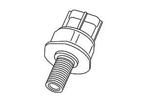
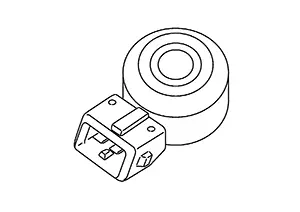
Knock Sensor
Component Description
Component Description
The knock sensor is attached to the cylinder block. It senses engine knocking using a piezoelectric element. A knocking vibration from the cylinder block is sensed as vibrational pressure. This pressure is converted into a voltage signal and sent to the ECM.
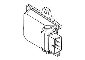
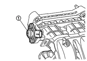
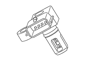
Manifold Absolute Pressure Sensor
Component Description
Component Description
FUNCTIONS WITHIN THE SYSTEM
ECM receives the manifold absolute pressure signal from the manifold absolute pressure sensor and performs various control.
INDIVIDUAL FUNCTION WITHIN THE SYSTEM
Manifold absolute pressure sensor detects the intake manifold pressure.
INDIVIDUAL OPERATION
Manifold absolute sensor uses a silicon diaphragm which is sensitive to the change in pressure. As the pressure increases, the voltage rises.
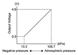
COMPONENT PARTS LOCATION
Manifold absolute pressure sensor is installed on the intake manifold.
Mass Air Flow Sensor (with Intake Air Temperature Sensor 1)
Component Description
Component Description
MASS AIR FLOW SENSOR
Mass air flow sensor is installed to the intake air path upstream of throttle and measures air flow rate.
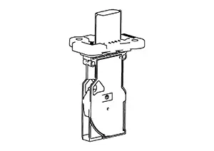
This mass air flow sensor is a backflow-detecting film and silicon element type sensor that can detects air flow rate of both direct flow and backflow. This mass air flow sensor outputs an air flow rate by using frequency signals.
The element part of this mass air flow sensor consists of a heater and temperature sensors installed to both top and bottom of the heater, one to each position. When air flows, the heat distribution around the heater changes and this produces a temperature difference between upstream and downstream. This temperature difference is detected as air flow rate.
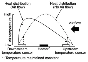
INTAKE AIR TEMPERATURE SENSOR
The intake air temperature sensor is built-into mass air flow sensor. The sensor detects intake air temperature and transmits a signal to the ECM.
The temperature sensing unit uses a thermistor which is sensitive to the change in temperature.
<Reference data>
|
Intake air temperature [┬░C (┬░F)] |
Voltage* (V) |
|---|---|
|
25 (77) |
2.0 ŌĆō 2.2 |
|
80 (176) |
3.0 ŌĆō 3.2 |
*: These data are reference values on the diagnosis tool.
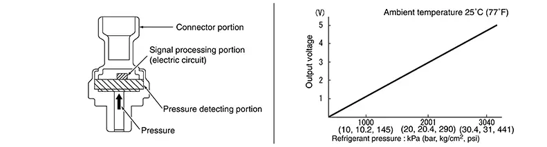
Refrigerant Pressure Sensor
Component Description
Component Description
The refrigerant pressure sensor is installed at the liquid tank of the air conditioner system. The sensor uses an electrostatic volume pressure transducer to convert refrigerant pressure to voltage. The voltage signal is sent to ECM, and ECM controls cooling fan system.
Reverse/neutral Position Switch
Component Description
Component Description
The reverse/neutral position switch is installed to manual transaxle case. The switch detects gear position is reverse/neutral.
Start/stop Off Switch
Component Description
Component Description
FUNCTIONS WITHIN THE SYSTEM
When the start/stop OFF switch is pressed, the internal indicator lamp (on information display) turns ON, and the start/stop system can be canceled.
INDIVIDUAL FUNCTION WITHIN THE SYSTEM
-
Turns the internal switch ON/OFF, controlling the start/stop OFF switch signal that is input into the BCM.
-
Turns the internal indicator lamp (on the information display) ON/OFF.
INDIVIDUAL OPERATION
-
When the start/stop OFF switch is turned ON, the internal indicator lamp (on the information display) turns ON, and the idle start/stop system does not operate.
-
When the start/stop OFF switch is turned OFF, the internal indicator lamp turns (on the information display) OFF, and the idle start/stop system operates.
COMPONENT PARTS LOCATION
The start/stop off switch is set on the front center of instrument panel.
Brake Pedal Position Switch
Component Description
Component Description
Brake pedal position switch are installed to brake pedal bracket.
ECM detects the state of the brake pedal by those two types of input (ON/OFF signal).
|
Brake pedal |
Brake pedal position switch |
|---|---|
|
Released |
ON |
|
Depressed |
OFF |
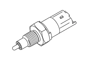
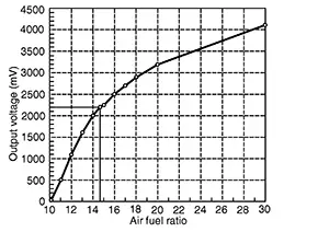
Air Fuel Ratio Sensor 1
Component Description
Component Description
Description
The A/F sensor 1 is mounted on the exhaust manifold, and transmits the signal of detected oxygen concentration in the exhaust gas to ECM.
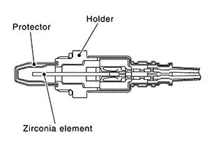
While O2 sensor changes output voltage by ON/OFF (rich/lean) mode within a narrow range of the stoichiometric ratio, the A/F sensor changes output voltage between 0 - 4 V for a wide range of air fuel ratio.
ECM judges the state of air fuel ratio with this signal, and precisely controls air fuel ratio to match the stoichiometric ratio.Also, the sensor is equiped with heater for maintaining the activated state.
A/F SENSOR 1 HEATER
A/F sensor 1 heater is integrated in the sensor.
The ECM performs ON/OFF duty control of the A/F sensor 1 heater corresponding to the engine operating condition to keep the temperature of A/F sensor 1 element within the specified range.
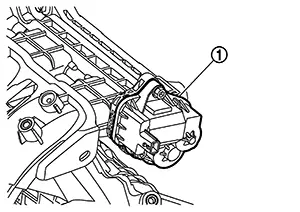
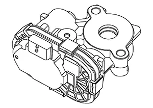
Egr Volume Control Valve
Component Description
Component Description
FUNCTIONS WITHIN THE SYSTEM
The control valve motor uses a DC motor to control the EGR flow from the exhaust manifold. The DC motor controls the valve position according to the driving conditions, in accordance with the commands from the ECM.
INDIVIDUAL FUNCTION WITHIN THE SYSTEM
The EGR volume control valve contains the control valve motor and control position sensor.
INDIVIDUAL OPERATION
EGR Volume Control Position Sensor
The control position sensor uses a permanent magnet and semiconductor element to detect the valve shaft angle and transmit a signal to the ECM. In this way, the ECM transmits a signal for controlling the valve position to the DC motor according to the driving conditions.
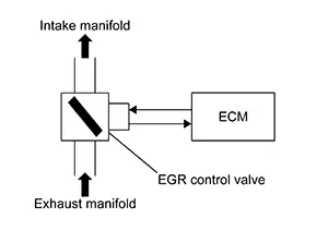
COMPONENT PARTS LOCATION
EGR volume control valve is installed to the exhaust side of cylinder head.
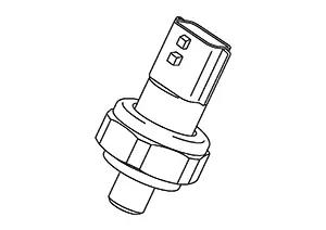
Engine Oil Pressure Sensor
Component Description
Component Description
The engine oil pressure (EOP) sensor is detects engine oil pressure and transmits a voltage signal to the ECM.
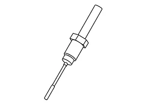
Exhaust Gas Temperature Sensor
Component Description
Component Description
Exhaust gas temperature sensor (EGT sensor) is installed exhaust manifold. The sensor uses a thermistor which is sensitive to the change in temperature. Electrical resistance of the thermistor decreases in response to the temperature rises.
<Reference data>
|
Exhaust gas temperature [┬░C (┬░F)] |
Voltage* (V) |
Resistance (kŌä”) |
|---|---|---|
|
100 (212) |
4.74 |
18.25 |
|
200 (392) |
4.00 |
4.00 |
|
400 (752) |
1.97 |
0.65 |
|
600 (1112) |
0.86 |
0.21 |
*: These data are reference values on the diagnosis tool.
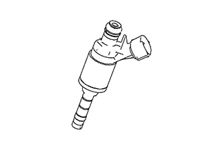
Fuel Injector
Component Description
Component Description
For the fuel injector, a high pressure fuel injector is used and this enables a high-pressure fuel injection at a high voltage within a short time. The ECM is equipped with an injector driver unit and actuates the fuel injector at a high voltage (approximately 65 V at the maximum).
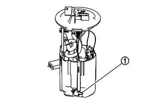
Fuel Level Sensor Unit and Fuel Pump
Component Description
Component Description
LOW PRESSURE FUEL PUMP
The low pressure fuel pump is integrated with a fuel pressure
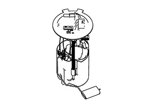
regulator and a fuel filter. This pump is build into the fuel tank.
FUEL LEVEL SENSOR
The fuel level sensor is mounted in the low pressure fuel pump.
The sensor detects a fuel level in the fuel tank and transmits a signal to the combination meter. The combination meter sends the fuel level sensor signal to the ECM via the CAN communication line.
It consists of two parts, one is mechanical float and the other is variable resistor. Fuel level sensor output voltage changes depending on the movement of the fuel mechanical float.
Intake Camshaft Position Sensor
Component Description
Component Description
FUNCTIONS WITHIN THE SYSTEM
Based on the intake camshaft position signal that is input , the ECM judges the intake camshaft position.
INDIVIDUAL FUNCTION WITHIN THE SYSTEM
The ECM inputs the voltage change caused by the change in magnetic field generated close to the intake camshaft position sensor and the timing of the change as signal voltage.
INDIVIDUAL OPERATION
The intake camshaft position sensor consists of a permanent magnet and Hall IC. When engine is running, the high and low parts of the teeth cause the gap with the sensor to change. The changing gap causes the magnetic field near the sensor to change. Due to the changing magnetic field, the voltage from the sensor changes.
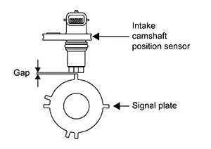
COMPONENT PARTS LOCATION
The intake camshaft position sensor is installed to the intake camshaft rear end.
Intake Valve Timing Control Solenoid Valve
Component Description
Component Description
Intake valve timing control solenoid valve is activated by ON/OFF pulse duty (ratio) signals from the ECM.
The intake valve timing control solenoid valve changes the oil amount and direction of flow through intake valve timing control unit or stops oil flow.
The longer pulse width advances valve angle.
The shorter pulse width retards valve angle.
When ON and OFF pulse widths become equal, the solenoid valve stops oil pressure flow to fix the intake valve angle at the control position.
Other materials:
Remote Keyless Entry Function
System Diagram
System Diagram
System Description
System Description
The Intelligent Key has the same functions as the
remote control entry system. Therefore, it can be used in the same
manner as the remote controller by operating the door lock/unlock
button.
OPERATION
Re ...
Diagnosis System (a/c Amp.)
Diagnosis Description
Diagnosis Description
CONSULT performs the following functions via CAN
communication with A/C amp.:
Diagnostic mode
CGW Status
Descrip ...
A/c Switch Assembly Signal Circuit
Diagnosis Procedure
Diagnosis Procedure
CHECK WITH SELF DIAGNOSTIC RESULT FUNCTION
CONSULT
Select ŌĆ£Self Diagnostic ResultŌĆØ mode of ŌĆ£HVACŌĆØ.
Check DTC.
...