Nissan Sentra B18 (2020-2025) Service Manual: Combination Switch Reading System
System Description
SYSTEM DIAGRAM
OUTLINE
-
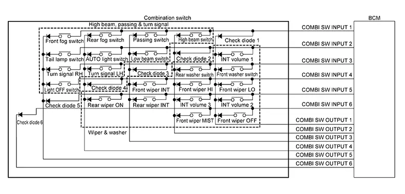
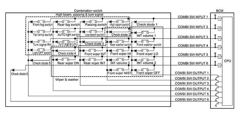
The BCM reads the status of the combination switch and recognizes the status of each switch.
-
The BCM has a combination of 6 input terminals (INPUT 1 - 6) and 6 output terminals (OUTPUT 1 - 6) and reads a maximum of 22 switch states.
COMBINATION SWITCH MATRIX
|
System |
INPUT 1 |
INPUT 2 |
INPUT 3 |
INPUT 4 |
INPUT 5 |
INPUT 6 |
|---|---|---|---|---|---|---|
|
OUTPUT 1 |
Check diode 1 |
INT volume 1 |
Front washer switch |
Front wiper LO |
INT volume 2 |
Front wiper OFF |
|
OUTPUT 2 |
High beam switch |
Check diode 2 |
Rear washer switch |
Front wiper HI |
INT volume 3 |
Front wiper MIST |
|
OUTPUT 3 |
Passing switch |
Low beam switch |
Check diode 3 |
Front wiper INT |
Rear wiper INT |
— |
|
OUTPUT 4 |
Rear fog switch |
AUTO light switch |
Turn signal LH |
Check diode 4 |
Rear wiper ON |
— |
|
OUTPUT 5 |
Front fog switch |
Tail lamp switch |
Turn signal RH |
Light OFF switch |
Check diode 5 |
— |
|
OUTPUT 6 |
— |
— |
— |
— |
— |
Check diode 6 |
COMBINATION SWITCH READING FUNCTION
Description
-
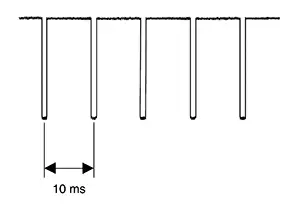
The BCM reads the status of the combination switch at 10 ms intervals normally.
-
The BCM operates as follows and judges the status of the combination switch:
-
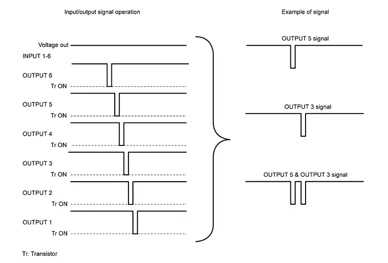
It operates the transistor on INPUT side in the following order: OUTPUT 6–> 5 –> 4 –> 3 –> 2 –> 1, and outputs voltage waveform.
-
The voltage waveform of OUTPUT corresponding to the formed circuit is input into the interface on the INPUT side if any (1 or more) switches are ON.
-
It reads this change of the voltage as the status signal of the combination switch.
-
Operation Example
In the following operation example, the combination
of the status signals of the combination switch is replaced as follows:
INPUT 1 - 6 to “ -
-  ” and OUTPUT 1
- 6 to “
” and OUTPUT 1
- 6 to “ -
-  ”.
”.
Example 1: When a switch (turn signal RH) is turned ON
-
The circuit between INPUT 3 (
 ) and OUTPUT 5 (
 ) is formed when the turn signal RH is
turned ON.
) is formed when the turn signal RH is
turned ON.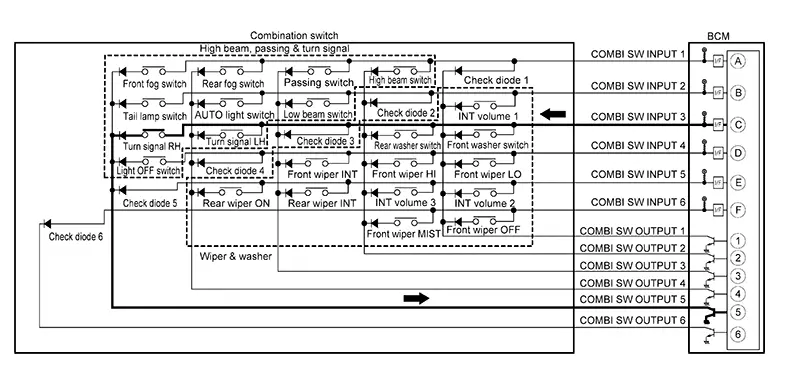
-
The BCM detects the combination switch status signal “
” when the signal of INPUT 3
is input
to OUTPUT 5. -
The BCM judges that the turn signal RH is ON when the signal “
” is detected.
Example 2: When multiple switches (front fog switch, turn signal RH) are turned ON
-
The circuits between INPUT 1 (
) and OUTPUT 5 () and between INPUT 3 () and
OUTPUT 5 () are formed when the front fog switch
and turn signal RH are turned ON.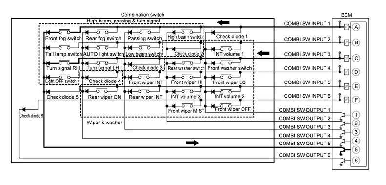
-
The BCM detects the combination switch status signal “
” when the signals of INPUT 1 and INPUT
3 are input to OUTPUT 5. -
The BCM judges that the front fog switch and turn signal RH are ON when the signal “
” is detected.
WIPER INTERMITTENT DIAL POSITION (WITH WIPER INTERMITTENT DIAL POSITION)
The BCM judges the wiper intermittent dial 1 - 5 by the status of INT volume 1, 2 and 3 switches.
|
Wiper intermittent dial position |
Switch status |
||
|---|---|---|---|
|
INT volume 1 |
INT volume 2 |
INT volume 3 |
|
|
1 |
ON |
ON |
OFF |
|
2 |
ON |
OFF |
OFF |
|
3 |
OFF |
OFF |
OFF |
|
4 |
OFF |
OFF |
ON |
|
5 |
OFF |
ON |
ON |

For details of wiper intermittent dial position, refer to System Description.
 Body Control System
System Description
System Description
OUTLINE
The BCM controls the various electrical components.
It inputs the information required for control via CAN communication
...
 Signal Buffer System
System Description
System Description
SYSTEM DIAGRAM
OUTLINE
The BCM has the signal transmission function that
outputs/transmits each input/received signal to each unit.
Signal trans ...
Other materials:
C161a-82 Abs System
Dtc Description
DTC Description
DTC DETECTION LOGIC
DTC No.
CONSULT screen terms
(Trouble diagnosis content)
DTC detection condition
...
Rear Brake Shoe. Inspection
Inspection
Inspection
INSPECTION
Remove the
inspection hole plug from the back plate. Refer to Exploded View.
Check the
brake shoe wear thickness (A).
Wear thickness (A)
: Refer to Rear Drum Brak ...
Wiring diagram
Ipdm e/r (intelligent power distribution module engine room)
Wiring diagram
...