Nissan Sentra B18 (2020-2025) Service Manual: Charging System :: Basic Inspection. Diagnosis and Repair Work Flow
Diagnosis and Repair Work Flow
Work Flow (with 165-Dss-5000p)
CHARGING SYSTEM DIAGNOSIS WITH 165-DSS-5000P
To test the charging system, use the following special service tool:
-
165-DSS-5000P battery and electrical diagnostic analyzer

Refer to the applicable Instruction Manual for proper charging system diagnosis procedures.
OVERALL SEQUENCE
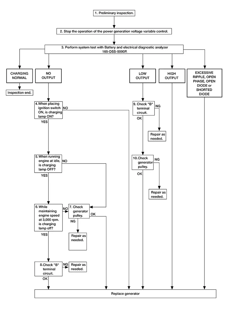
DETAILED FLOW
Note:
To ensure a complete and thorough diagnosis, the battery, stater and generator test segments must be done as a set from start to finish.
-
PRELIMINARY INSPECTION
-
Perform the preliminary inspection. Refer to Diagnosis Procedure.
GO TO 2.
-
-
STOP POWER GENERATION VOLTAGE VARIABLE CONTROL SYSTEM
-
Stop the operation of the power generation voltage variable control in either of the following procedures.
 CONSULT
-
After selecting “ENGINE”, set the DUTY value of “ALTERNATOR DUTY” to 0 % by selecting “ALTERNATOR DUTY” of “Active Test”. Continue “Active Test” until the end of inspection. (When the DUTY value is 0 or 100 %, the normal power generation is performed according to the characteristic of the IC regulator of the generator.)
-
Ignition switch OFF, and disconnect the battery current sensor connector. [However, DTC (P1550–P1554) of the engine might remain. After finishing the inspection, connect the battery current sensor connector and erase the self diagnosis results history of the engine using CONSULT.]
-
GO TO 3.
-
-
DIAGNOSIS WITH 165-DSS-5000P
-
Perform the system test using battery and electrical diagnostic analyzer 165-DSS-5000P. Refer to the applicable Instruction Manual for proper testing procedures.
Test result
CHARGING NORMAL>>Charging system is normal and will also show “DIODE RIPPLE” test result.
NO OUTPUT>>GO TO 4.
LOW OUTPUT>>GO TO 9.
HIGH OUTPUT>>Replace the generator. Refer to Removal and Installation.
EXCESSIVE RIPPLE, OPEN PHASE, OPEN DIODE or SHORTED DIODE>>Replace the generator. Refer to Removal and Installation. Perform system test again using the 165-DSS-5000P battery and electrical diagnostic analyzer to confirm repair.
-
-
INSPECTION WITH CHARGE WARNING LAMP (IGNITION SWITCH IS ON)
-
Ignition switch ON.
Does the charge warning lamp illuminate?
YES>>GO TO 5.
NO>>Replace the generator. Refer to Removal and Installation.
-
-
INSPECTION WITH CHARGE WARNING LAMP (IDLING)
-
Start the engine and run it at idle.
Does the charge warning lamp turn OFF?
YES>>GO TO 6.
NO>>GO TO 7.
-
-
INSPECTION WITH CHARGE WARNING LAMP (ENGINE AT 3,000 RPM)
-
Increase and maintain the engine speed at 3,000 rpm.
Does the charge warning lamp remain off?
YES>>GO TO 8.
NO>>GO TO 7.
-
-
INSPECTION OF GENERATOR PULLEY
-
Check generator pulley. Refer to Inspection.
Is generator pulley normal?
YES>>Replace the generator. Refer to Removal and Installation.
NO>>Repair as needed.
-
-
“B” TERMINAL CIRCUIT INSPECTION
-
Check “B” terminal circuit. Refer to Diagnosis Procedure.
Is “B” terminal circuit normal?
YES>>Replace the generator. Refer to Removal and Installation.
NO>>Repair as needed.
-
-
“B” TERMINAL CIRCUIT INSPECTION
-
Check “B” terminal circuit. Refer to Diagnosis Procedure.
Is “B” terminal circuit normal?
YES>>GO TO 10.
NO>>Repair as needed.
-
-
INSPECTION OF GENERATOR PULLEY
-
Check generator pulley. Refer to Inspection.
Is generator pulley normal?
YES>>Replace the generator. Refer to Removal and Installation.
NO>>Repair as needed.
-
Work Flow (without 165-Dss-5000p)
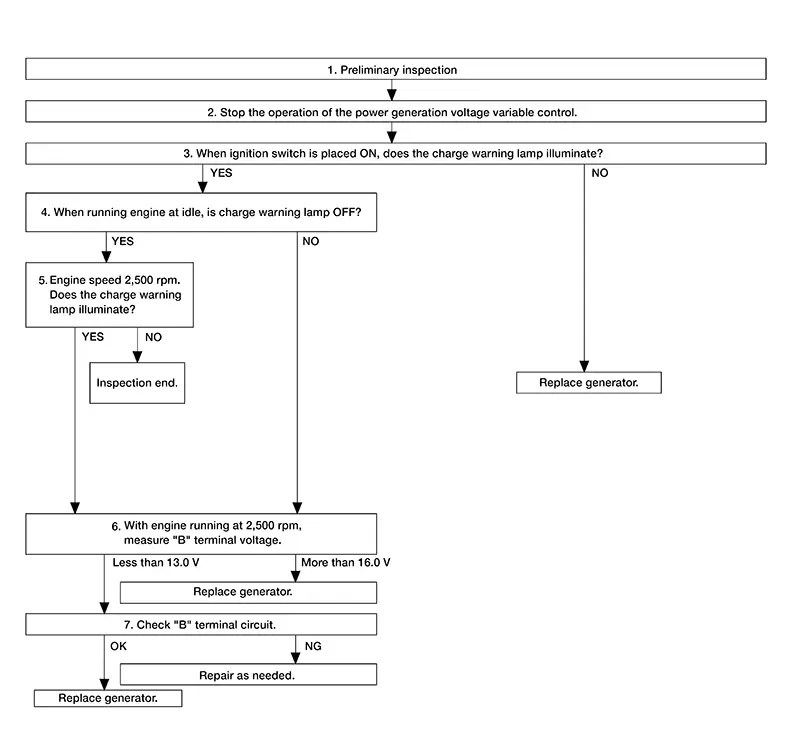
OVERALL SEQUENCE
Before performing a generator test, make sure that the battery is fully charged. A 30-volt voltmeter and suitable test probes are necessary for the test.
-
Before starting, inspect the fusible link.
-
Use fully charged battery.
DETAILED FLOW
-
PRELIMINARY INSPECTION
-
Perform the preliminary inspection. Refer to Diagnosis Procedure.
GO TO 2.
-
-
STOP POWER GENERATION VOLTAGE VARIABLE CONTROL SYSTEM
-
CONSULT
Stop the operation of the power generation voltage variable control in either of the following procedures:
-
After selecting “ENGINE”, set the DUTY value of “ALTERNATOR DUTY” to 0 % by selecting “ALTERNATOR DUTY” with “Active Test”. Continue “Active Test” until the end of inspection. (When the DUTY value is 0 or 100 %, the normal power generation is performed according to the characteristic of the IC regulator of the generator.)
-
Ignition switch OFF, and disconnect the battery current sensor connector. [However, DTC (P1550 - P1554) of the engine might remain. After finishing the inspection, connect the battery current sensor connector and erase the self-diagnostic results history of the engine.]
-
GO TO 3.
-
-
INSPECTION WITH CHARGE WARNING LAMP (IGNITION SWITCH IS ON)
-
When ignition switch is placed ON.
Does the charge warning lamp illuminate?
YES>>GO TO 4.
NO>>Replace the generator. Refer to Removal and Installation.
-
-
INSPECTION WITH CHARGE WARNING LAMP (IDLING)
-
Start the engine and run it at idle.
Does the charge warning lamp turn OFF?
YES>>GO TO 5.
NO>>GO TO 6.
-
-
INSPECTION WITH CHARGE WARNING LAMP (ENGINE AT 2,500 RPM)
-
Increase and maintain the engine speed at 2,500 rpm.
Does the charge warning lamp illuminate?
YES>>GO TO 6.
NO>>Inspection End.
-
-
MEASURE “B” TERMINAL VOLTAGE
-
Start engine. With engine running at 2,500 rpm, measure “B” terminal voltage.
What voltage does the measurement result show?
Less than 13.0 V>>GO TO 7.
More than 16.0 V>>Replace the generator. Refer to Removal and Installation.
-
-
“B” TERMINAL CIRCUIT INSPECTION
-
Check “B” terminal circuit. Refer to Diagnosis Procedure.
Is the inspection result normal?
YES>>Replace the generator. Refer to Removal and Installation.
NO>>Repair as needed.
-
Other materials:
Tire Pressure Monitoring System (TPMS)
Each tire, including the spare (if provided),
should be checked monthly when cold and inflated
to the inflation pressure recommended by
the vehicle manufacturer on the vehicle placard
or tire inflation pressure label. (If your vehicle has
tires of a different size than the size indicated on
th ...
Service data and specifications
(sds)
Periodical Maintenance Specification
ENGINE COOLANT CAPACITY (APPROXIMATE)
Radiator
Thermostat
Water Control Valve
...
Tcm branch line circuit
Diagnosis procedure
1.Check connector
Turn the ignition switch off.
Disconnect the battery cable from the negative terminal.
Check the following terminals and connectors for damage, bend and loose
connection (unit side and connector
side).
Tcm
Harness connector F50
Harness co ...