Nissan Sentra Service Manual: C1109 Power and ground system
DTC Logic
DTC DETECTION LOGIC
| DTC | Display Item | Malfunction detected condition | Possible causes |
| C1109 | BATTERY VOLTAGE [ABNORMAL] |
|
|
DTC CONFIRMATION PROCEDURE
1.CHECK SELF DIAGNOSTIC RESULT
 With CONSULT.
-
Turn the ignition switch ON.
-
Perform self diagnostic result.
Is DTC C1109 detected? YES >> Proceed to diagnosis procedure. Refer to BRC-62, "Diagnosis Procedure".
NO >> Inspection End.
Diagnosis Procedure
Regarding Wiring Diagram information, refer to BRC-44, "Wiring Diagram".
1.Connector inspection
-
Turn ignition switch OFF.
-
Disconnect abs actuator and electric unit (control unit) connectors.
-
Check connectors and terminals for deformation, disconnection, looseness or damage.
Is the inspection result normal? Yes >> go to 2
No >> repair or replace as necessary.
2.Check abs actuator and electric unit (control unit) ignition power supply circuit
Check voltage between abs actuator and electric unit (control unit) connector e33 terminal 28 and ground.
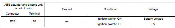
Is the inspection result normal? Yes >> go to 3
No >> repair or replace malfunctioning components.
3.Check abs actuator and electric unit (control unit) ground circuit
Turn ignition switch OFF.
Check continuity between abs actuator and electric unit (control unit) connector e33 terminals 13, 38 and ground.
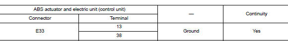
Is the inspection result normal? YES >> Replace ABS actuator and electric unit (control unit). Refer to BRC-110, "Removal and Installation".
NO >> Repair or replace malfunctioning components.
 C1105, C1106, C1107, C1108 Wheel sensor
Description
When the sensor rotor rotates, the magnetic field changes. It
converts the magnetic field changes to current
signals (rectangular wave) and transmits them to the ABS actuator and elec ...
 1110, C1170 ABS Actuator and electric unit (control unit)
DTC Logic
DTC DETECTION LOGIC
DTC
Display item
Malfunction detected condition
Possible cause
C1110
CONTROLLER FAILURE
When there is an internal malfunction in the ABS ...
Other materials:
Unit disassembly and assembly
TORQUE CONVERTER AND CONVERTER HOUSING OIL SEAL
Exploded View
Transaxle assembly
Torque converter
Converter housing oil seal
: Apply CVT Fluid
Disassembly
Remove transaxle assembly.
Remove torque converter.
CAUTION:
Do not damage the bushing on the inside of torque con ...
Wiper and washer fuse
Description
Diagnosis procedure
1. Check fuses
Check that the following fuses are not blown.
Is the fuse blown?
Yes >> replace the blown fuse after repairing the affected circuit.
No >> inspection end. ...
Basic inspection
Diagnosis and repair work flow
Work flow
Overall sequence
Detailed flow
1.Get information for symptom
Get detailed information from the customer about the symptom (the
condition and the environment when
the incident/malfunction occurs).
Check operation condition of the component o ...
