Nissan Sentra B18 (2020-2025) Service Manual: Basic Inspection
Diagnosis and Repair Workflow
Work Flow
Work Flow
OVERALL SEQUENCE
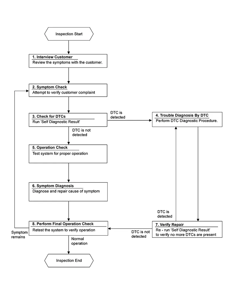
DETAILED FLOW
-
INTERVIEW CUSTOMER
-
Interview the customer to obtain as much information as possible about the conditions and environment under which the malfunction occurred.
GO TO 2.
-
-
SYMPTOM CHECK
-
Verify symptoms.
GO TO 3.
-
-
CHECK FOR DTCS
-
 CONSULT
-
Ignition switch ON.
-
Select “Self Diagnostic Result� mode of “HVAC�.
-
Check DTC.
-
Is any DTC detected?
YES >>GO TO 4.
NO >>GO TO 5.
-
-
TROULE DIAGNOSIS BY DTC
-
Perform the diagnostic procedure for the detected DTC. Refer to DTC Inspection Priority Chart.
GO TO 7.
-
-
OPERATION CHECK
-
Perform the operation check. Refer to Work Procedure.
GO TO 6.
-
-
SYMPTOM DIAGNOSIS
-
Check the symptom diagnosis table. Refer to Symptom Table.
GO TO 8.
-
-
VERIFY REPAIR
-
CONSULT
-
Ignition switch ON.
-
Select “Self Diagnostic Result� mode of “HVAC�.
-
Check DTC.
-
Is any DTC detected?
YES >>GO TO 4.
NO >>GO TO 8.
-
-
PERFORM FINAL OPERATION CHECK
-
Perform the operation check. Refer to Work Procedure.
Does it operate normally?
YES >>Inspection End.
NO >>GO TO 2.
-
Operation Inspection
Work Procedure
Work Procedure
DESCRIPTION
The purpose of the operational check is to check that the individual system operates normally.
|
Check condition |
: Engine running at normal operating temperature. |
|
Check condition |
: Blower control dial in OFF position. |
|
Check condition |
: REC off (LED extinguished). |
|
Check condition |
: VENT selected (LED illuminated). |
|
Check condition |
: DEF off (LED extinguished). |
OPERATION INSPECTION
-
CHECK BLOWER
-
-
Rotate the blower control dial clockwise one detent. Blower should operate on low speed.
-
Rotate the blower control dial one detent at a time, and continue checking blower speed until all speeds are checked.
-
Leave blower on maximum speed.
-
Is the test result normal?
YES >>GO TO 2.
NO >>Refer to Diagnosis Procedure.
-
-
CHECK A/C SWITCH LED
-
-
Press A/C switch.
-
A/C switch indicator should turn ON.
-
Is the test result normal?
YES >>GO TO 3.
NO >>Refer to Diagnosis Procedure.
-
-
CHECK A/C SWITCH
-
Confirm that the A/C compressor clutch engages (sound or visual inspection).
Is the test result normal?
YES >>GO TO 4.
NO >>Refer to Diagnosis Procedure.
-
-
CHECK A/C SWITCH ASSEMBLY MODE LEDS
-
-
Press D/F (
 ), FOOT (
 ), B/L
 , and VENT
  , MAX A/C, and
DEF (
, MAX A/C, and
DEF ( ).
). -
Each button indicator should illuminate.
-
Is the test result normal?
YES >>GO TO 5.
NO >>Refer to Diagnosis Procedure.
-
-
CHECK DISCHARGE AIR
-
-
Press D/F (
), FOOT (), B/L
, and VENT and DEF (). -
Confirm that discharge air comes out according to the air distribution table. Refer to Door Control.
-
Is the test result normal?
YES >>GO TO 6.
NO >>Refer to Symptom Table.
-
-
CHECK REC LED
-
-
Press DEF (
) and make sure LED is off. -
Make sure VENT (
) or B/L ()
is selected. -
Press REC (
 ) switch one time. REC indicator should
illuminate.
) switch one time. REC indicator should
illuminate. -
Press REC (
) switch one more time. REC indicator
should go off.
-
Is the test result normal?
YES >>GO TO 7.
NO >>Refer to Diagnosis Procedure.
-
-
CHECK INTAKE DOOR OPERATION
-
-
Press REC (
) switch one time. REC indicator should
illuminate. -
Listen to the sound of the air coming out of the vent.
-
Press REC (
) switch one more time. REC indicator
should go off. -
There should be an audible change to the sound of the air flowing out of the vent.
-
Is the test result normal?
YES >>GO TO 8.
NO >>Refer to Diagnosis Procedure.
-
-
CHECK TEMPERATURE DECREASE
-
-
Press A/C switch.
-
Rotate temperature control dial counterclockwise until maximum cold.
-
Check for cold air at selected discharge air outlets.
-
Is the test result normal?
YES >>GO TO 9.
NO >>Refer to Component Function Check.
-
-
CHECK TEMPERATURE INCREASE
-
-
Rotate temperature control dial clockwise until maximum hot.
-
Check for hot air at appropriate discharge air outlets.
-
Is the test result normal?
YES >>Inspection End.
NO >>Refer to Component Function Check.
-
System Setting
Target Evaporator Temp Upper Limit
Target Evaporator Temp Upper Limit
DESCRIPTION
Set the target evaporator temperature upper limit.
HOW TO SET
CONSULT
Select “TARGET EVAPORATOR TEMP UPPER LIMIT SETTING� in “Work support� mode of “HVAC�.
|
Work support items |
Display |
|---|---|
|
TARGET EVAPORATOR TEMP UPPER LIMIT SETTING |
Initial Setting |
|
Low |
|
|
Middle |
|
|
High |
Foot Position Setting Trimmer
Foot Position Setting Trimmer
DESCRIPTION
In FOOT mode, the air blowing to DEF can change ON/OFF.
HOW TO SET
CONSULT
Select “BLOW SET� in “Work support� mode of “HVAC�.
|
Work support items |
Display |
Defroster door position |
|
|---|---|---|---|
|
Auto control |
Manual control |
||
|
BLOW SET |
Mode1 (initial status) |
OPEN |
CLOSE |
|
Mode2 |
OPEN |
OPEN |
|
|
Mode3 |
CLOSE |
OPEN |
|
|
Mode4 |
CLOSE |
CLOSE |
|

When the battery cable is disconnected from the negative terminal or when the battery voltage becomes 10V or less, the setting of the discharge air mix ratio in FOOT mode may be cancelled.
Other materials:
Basic Inspection
Additional Service When Replacing Adas Control Unit 2
Description
Description
Always perform the ADAS control unit 2 configuration after
replacing the ADAS control unit 2.
Work Procedure
Work Procedure
ADAS CONTROL UNIT 2 CONFIGURATION
CONSULT
Perform the ADA ...
Fuel Injector
Component Function Check
Component Function Check
INSPECTION START
Turn ignition switch to START.
Are any cylinders ignited?
YES >>
GO TO
2.
NO >>
Refer to Diagnosis Procedure.
CHECK FUEL INJECTOR FUNCTION
...
Back-Up Lamp Relay Circuit
Component Function Check
Component Function
Check
CHECK BACK-UP LAMP OPERATION
Ignition switch ON.
With operating the shift selector, check that the
back-up lamp is turn ...