Nissan Sentra B18 (2020-2025) Service Manual: B2e10 Mic Out Signal
Dtc Description
DTC Description
DTC DETECTION LOGIC
|
DTC No. |
CONSULT screen terms (Trouble diagnosis content) |
DTC detection condition |
|
|---|---|---|---|
|
B2E10-11 |
MIC OUT SIGNAL (MIC OUT SIGNAL) |
Diagnosis condition |
When ignition switch is ON |
|
Signal (terminal) |
Microphone signal |
||
|
Threshold |
ŌĆö |
||
|
Diagnosis delay time |
1 second or more |
||
|
B2E10-12 |
Diagnosis condition |
When ignition switch is ON |
|
|
Signal (terminal) |
Microphone signal |
||
|
Threshold |
ŌĆö |
||
|
Diagnosis delay time |
1 second or more |
||
POSSIBLE CAUSE
-
11: Sound signal circuit is short to ground
-
12: Sound signal circuit is short to battery
-
AV control unit
-
TCU
FAIL-SAFE
Telematics sound is not output
Confirmation Procedure
Confirmation Procedure
-
PERFORM DTC CONFIRMATION PROCEDURE
-
 CONSULT
-
Ignition switch ON.
-
Ignition switch OFF and wait at least 30 seconds.
-
Ignition switch ON and wait at least 30 seconds or more.
-
Select ŌĆ£Self Diagnostic ResultŌĆØ mode of ŌĆ£IVCŌĆØ.
-
Check DTC.
-
Is DTC B2E10 detected?
YES >>Proceed to DTC Diagnosis Procedure.
NO >>To check malfunction symptom before repair: Refer to Intermittent Incident.
NO >>Confirmation after repair: Inspection End.
-
Dtc Diagnosis Procedure
DTC Diagnosis Procedure
-
DETERMINE MALFUNCTION TYPE
-
CONSULT
-
Ignition switch ON.
-
Ignition switch OFF and wait at least 30 seconds.
-
Ignition switch ON and wait at least 30 seconds or more.
-
Select ŌĆ£Self Diagnostic ResultŌĆØ mode of ŌĆ£IVCŌĆØ.
-
Check DTC.
-
Is DTC B2E10ŌĆō11 or 12 detected?
YES >>11 ŌĆō GO TO 2.
YES >>12 ŌĆō GO TO 3.
NO >>Refer to Intermittent Incident.
-
-
CHECK TEL VOICE SIGNAL CIRCUITS FOR SHORT TO GROUND
-
-
Ignition switch OFF.
-
Disconnect AV control unit and TCU connectors.
-
Check the continuity between TCU connector and ground.
TCU
ŌĆö
Continuity
Connector
Terminal
M160
12
Ground
No
-
Is the inspection result normal?
YES >>GO TO 4.
NO >>Repair or replace harness or connectors.
-
-
CHECK TEL VOICE SIGNAL CIRCUIT FOR SHORT TO POWER SUPPLY
-
-
Ignition switch OFF.
-
Disconnect AV control unit connector and TCU connector.
-
Ignition switch ON.
-
Check the voltage between TCU connector and ground.
(+)
(-)
Voltage
(Approx.)
TCU
Connector
Terminal
M160
12
Ground
0 V
-
Is the inspection result normal?
YES >>GO TO 4.
NO >>Repair or replace harness or connectors.
-
-
CHECK TEL VOICE SIGNAL
-
-
Connect AV control unit connector and TCU connector.
-
Ignition switch ON.
-
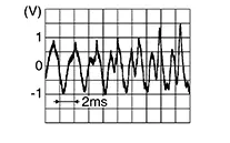
Check signal between the terminals of TCU connector.
TCU
(ŌłÆ)
Condition
Reference value
Connector
(+)
Terminal
M160
12
Ground
Speak into microphone.
-
Is the inspection result normal?
YES >>Replace AV control unit. Refer to Removal and Installation.
NO >>Replace TCU. Refer to Removal and Installation.
-
Other materials:
Basic Inspection
Diagnosis and Repair Work Flow
Work Flow
Work Flow
OVERALL SEQUENCE
DETAILED FLOW
INTERVIEW FOR MALFUNCTION
It is also important to clarify the customer
concerns before starting the inspection. Interview the
customer about the concerns carefully and ...
Heater and air conditioner (automatic)
AUTO (automatic) climate control button / temperature control dial (driver's
side)
Display screen
Heated seat switches (if so equipped)
SYNC button / temperature control dial (passenger's side)
A/C (air conditioner) button
Air recirculation button
A ...
B2fa9-11 Shift Position
Dtc Description
DTC Description
DTC DETECTION LOGIC
DTC No.
CONSULT screen items
(Trouble diagnosis
content)
DTC detecting condition
...