Nissan Sentra B18 (2020-2025) Service Manual: After Replacing ECM
-
CHECK ŌĆśOPERATION LOGŌĆÖ
 With CONSULT
Check Operation Log saved before replacing ECM, according to the procedure of ŌĆ£ProgrammingŌĆØ in CONSULT Operation Manual.
Note:
For the Nissan Sentra vehicle that the programming is to be performed, check if Operation Log of Vehicle Identification Number (VIN) is in Saved Data List.
Is there an applicable Operation Log in the Saved Data List?
YES >>GO TO 2.
NO >>GO TO 3.
-
PERFORM ECM PROGRAMMING
With CONSULTPerform ECM programming, according to ŌĆ£ProgrammingŌĆØ of CONSULT Operation Manual. Refer to CONSULT Operation Manual.
CAUTION:
During programming, maintain the following conditions:
-
Ignition switch: ON
-
Electric load: OFF
-
Brake pedal: Not depressed
-
Battery voltage: 12 ŌĆō 13.5 V (Check the value displayed on the CONSULT screen.)
GO TO 5.
-
-
READ IN ECM PART NUMBER BY ŌĆśFAST LINKEDŌĆÖ
Obtain ECM part number by NISSAN PARTS CATALOGUE GLOBAL Web-FAST, according to the procedure of ŌĆśFAST linkedŌĆÖ in CONSULT Operation Manual. Refer to CONSULT Operation Manual.
Note:
ŌĆśFAST linkedŌĆÖ allows an appropriate programming by obtaining ECU part number from NISSAN PARTS CATALOGUE GLOBAL Web-FAST even when the part number cannot be obtained from the old ECU used before replacing with a new one.
>>GO TO 4.
-
PERFORM ECM PROGRAMMING (FAST LINKED)
With CONSULTPerform ECM programming according to the procedure of FAST linked in CONSULT Operation Manual. Refer to CONSULT Operation Manual.
CAUTION:
During programming, maintain the following conditions:
-
Ignition switch: ON
-
Electric load: OFF
-
Brake pedal: Not depressed
-
Battery voltage: 12 ŌĆō 13.5 V (Check the value displayed on the CONSULT screen.)
GO TO 5.
-
-
PERFORM INITIALIZATION OF IVIS (NATS) SYSTEM AND REGISTRATION OF ALL IVIS (NATS) IGNITION KEY IDS
Refer to Work Procedure.
>>GO TO 6.
-
CHECK ECM DATA STATUS
Check if the data is successfully copied from the ECM at Step 1 (before replacement) and saved in CONSULT.
Is the data saved successfully?
YES >>GO TO 7.
NO >>GO TO 8.
-
WRITE ECM DATA
With CONSULT-
Select ŌĆ£WRITING DATA FOR REPLC CPUŌĆØ in ŌĆ£WORK SUPPORTŌĆØ mode of ŌĆ£ENGINEŌĆØ using CONSULT.
-
Follow the instruction of CONSULT display.
The data saved by ŌĆ£SAVING DATA FOR REPLC CPUŌĆØ is written to ECM.
>>GO TO 9.
-
-
PERFORM VIN REGISTRATION
Refer to Work Procedure.
>>GO TO 9.
-
PERFORM ACCELERATOR PEDAL RELEASED POSITION LEARNING
Perform accelerator pedal released position learning. Refer to Work Procedure.
>>GO TO 10.
-
PERFORM THROTTLE VALVE CLOSED POSITION LEARNING
Perform throttle valve closed position learning. Refer to Work Procedure.
>>GO TO 11.
-
PERFORM IDLE AIR VOLUME LEARNING
Perform idle air volume learning. Refer to Work Procedure.
>>END
Accelerator Pedal Released Position Learning
Work Procedure
Work Procedure
Description
Accelerator Pedal Released Position Learning is a function of ECM to learn the fully released position of the accelerator pedal by monitoring the accelerator pedal position sensor output signal. It must be performed each time harness connector of accelerator pedal position sensor or ECM is disconnected.
Work Procedure
-
START
-
Make sure that accelerator pedal is fully released.
-
Turn ignition switch ON and wait at least 2 seconds.
-
Turn ignition switch OFF and wait at least 10 seconds.
-
Repeat steps 2 to 3 for three times.
END
-
Basic Inspection
Work Procedure
Work Procedure
-
INSPECTION START
-
Check service records for any recent repairs that may indicate a related malfunction, or a current need for scheduled maintenance.
-
Open engine hood and check the following:
-
Harness connectors for improper connections
-
Wiring harness for improper connections, pinches and cut
-
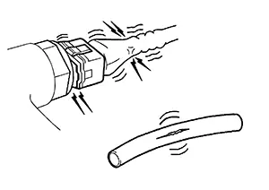
Vacuum hoses for splits, kinks and improper connections
-
Hoses and ducts for leaks
-
Air cleaner clogging
-
Gasket
-
-
Confirm that electrical or mechanical loads are not applied.
-
Headlamp switch is OFF.
-
Air conditioner switch is OFF.
-
Rear window defogger switch is OFF.
-
Steering wheel is in the straight-ahead position, etc.
-
-
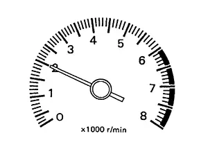
Start engine and warm it up until engine coolant temperature indicator points to the middle of gauge.
Ensure engine stays below 1,000 rpm.
-
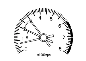
Run engine at about 2,000 rpm for about 2 minutes under no load.
-
Make sure that no DTC is displayed with CONSULT or Diagnostic Test Mode II (self-diagnostic results).
Is any DTC detected?
YES >>GO TO 2.
NO >>GO TO 3.
-
-
REPAIR OR REPLACE
Repair or replace components as necessary according to corresponding Diagnostic Procedure.
>>GO TO 3.
-
CHECK TARGET IDLE SPEED
-
Run engine at about 2,000 rpm for about 2 minutes under no load.
-
Rev engine (2,000 to 3,000 rpm) two or three times under no load, then run engine at idle speed for about 1 minute.
-
Check idle speed.
For procedure, Refer to IDLE SPEED : Periodic Maintenance.
For specification, Refer to IDLE SPEED : Service Data.
Is the inspection result normal?
YES >>GO TO 10.
NO >>GO TO 4.
-
-
PERFORM ACCELERATOR PEDAL RELEASED POSITION LEARNING
-
Stop the engine.
-
Perform accelerator pedal released position learning. Refer to Work Procedure.
GO TO 5.
-
-
PERFORM THROTTLE VALVE CLOSED POSITION LEARNING
Perform throttle valve closed position learning. Refer to Work Procedure.
>>GO TO 6.
-
PERFORM IDLE AIR VOLUME LEARNING
Perform idle air volume learning. Refer to Work Procedure.
Is Idle Air Volume Learning carried out successfully?
YES >>GO TO 7.
NO >>Follow the instruction of IDLE AIR VOLUME LEARNING. Then GO TO 4.
-
CHECK TARGET IDLE SPEED AGAIN
-
Start engine and warm it up to normal operating temperature.
-
Check idle speed.
For procedure, Refer to IDLE SPEED : Periodic Maintenance.
For specification, Refer to IDLE SPEED : Service Data.
Is the inspection result normal?
YES >>GO TO 10.
NO >>GO TO 8.
-
-
DETECT MALFUNCTIONING PART
Check the Following.
-
Check intake camshaft position sensor and circuit. Refer to DTC Description.
-
Check exhaust camshaft position sensor and circuit. Refer to DTC Description.
-
Check crankshaft position sensor and circuit. Refer to DTC Description.
Is the inspection result normal?
YES >>GO TO 9.
NO >>Repair or replace. Then GO TO 4.
-
-
CHECK ECM FUNCTION
Substitute another known-good ECM to check ECM function. (ECM may be the cause of an incident, but this is a rare case.)
>>GO TO 4.
-
CHECK IGNITION TIMING
-
Run engine at idle.
-
Check ignition timing with a timing light.
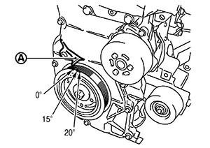

: Timing indicator
For procedure, Refer to IGNITION TIMING : Periodic Maintenance.
For specification, Refer to IGNITION TIMING : Service Data.
Is the inspection result normal?
YES >>GO TO 19.
NO >>GO TO 11.
-
-
PERFORM ACCELERATOR PEDAL RELEASED POSITION LEARNING
-
Stop the engine.
-
Perform accelerator pedal released position learning. Refer to Work Procedure.
GO TO 12.
-
-
PERFORM THROTTLE VALVE CLOSED POSITION LEARNING
Perform throttle valve closed position learning. Refer to Work Procedure.
>>GO TO 13.
-
PERFORM IDLE AIR VOLUME LEARNING
Perform idle air volume learning. Refer to Work Procedure.
Is Idle Air Volume Learning carried out successfully?
YES >>GO TO 14.
NO >>Follow the instruction of IDLE AIR VOLUME LEARNING. Then GO TO 4.
-
CHECK TARGET IDLE SPEED AGAIN
-
Start engine and warm it up to normal operating temperature.
-
Check idle speed.
For procedure, Refer to IDLE SPEED : Periodic Maintenance.
For specification, Refer to IDLE SPEED : Service Data.
Is the inspection result normal?
YES >>GO TO 15.
NO >>GO TO 17.
-
-
CHECK IGNITION TIMING AGAIN
-
Run engine at idle.
-
Check ignition timing with a timing light.
: Timing indicator
For procedure, Refer to IGNITION TIMING : Periodic Maintenance.
For specification, Refer to IGNITION TIMING : Service Data.
Is the inspection result normal?
YES >>GO TO 19.
NO >>GO TO 16.
-
-
CHECK TIMING CHAIN INSTALLATION
Check timing chain installation. Refer to Removal and Installation.
Is the inspection result normal?
YES >>GO TO 17.
NO >>Repair the timing chain installation. Then GO TO 4.
-
DETECT MALFUNCTIONING PART
Check the Following.
-
Check intake camshaft position sensor and circuit. Refer to DTC Description.
-
Check exhaust camshaft position sensor and circuit. Refer to DTC Description.
-
Check crankshaft position sensor and circuit. Refer to DTC Description.
Is the inspection result normal?
YES >>GO TO 18.
NO >>Repair or replace. Then GO TO 4.
-
-
CHECK ECM FUNCTION
Substitute another known-good ECM to check ECM function. (ECM may be the cause of an incident, but this is a rare case.)
>>GO TO 4.
-
INSPECTION END
If ECM is replaced during this BASIC INSPECTION procedure, Refer to Work Procedure.
>>INSPECTION END
Cumulative Battery Discharge Current Clear
Description
Description
Cumulative Battery Discharge Current Clear is a function of ECM to erase the cumulative battery discharge current. It must be performed when battery is replaced. (For details, refer to Work Procedure.)
Work Procedure
Work Procedure
-
ERASE CUMULATIVE BATTERY DISCHARGE CURRENT
With CONSULT-
Turn ignition switch ON.
-
Select ŌĆ£CML B/DCHRG CRNT CLEARŌĆØ in ŌĆ£WORK SUPPORTŌĆØ mode of ŌĆ£ENGINEŌĆØ using CONSULT.
-
Touch ŌĆ£CLEARŌĆØ and erase cumulative battery discharge current.
INSPECTION END
-
Egr Volume Control Valve Position Learning
Work Procedure
Work Procedure
DESCRIPTION
EGR Volume Control Valve Closed Position Learning is a function of ECM to learn the fully closed position of the EGR volume control valve by monitoring the EGR volume control valve output signal. It must be performed under any of the following conditions:
-
Replacement EGR volume control valve
WORK PROCEDURE
-
START
-
Turn ignition switch ON.
-
Select ŌĆ£EGR Control Valve Closed Position LearningŌĆØ in ŌĆ£WORK SUPPORTŌĆØ of ŌĆ£ENGINEŌĆØ.
-
Touch ŌĆ£StartŌĆØ.
-
Turn ignition switch OFF and wait at least 3 seconds.
Note:
Learning is completed during a self-shutoff of the EGR volume control valve.
END
-
Fuel Pressure Check
Work Procedure
Work Procedure
FUEL PRESSURE RELEASE
-
FUEL PRESSURE RELEASE
With CONSULT-
Turn ignition switch ON.
-
Perform ŌĆ£ENGINEŌĆØ in ŌĆ£WORK SUPPORTŌĆØ mode with CONSULT.
-
Start the engine.
-
After engine stalls, crank it two or three times to release all fuel pressure.
-
Turn ignition switch OFF.
 Without CONSULT
-
Remove fuel pump fuse located in IPDM E/R.
-
Start the engine.
-
After engine stalls, crank it two or three times to release all fuel pressure.
-
Turn ignition switch OFF.
-
Reinstall fuel pump fuse after servicing fuel system.
INSPECTION END
-
FUEL PRESSURE CHECK
-
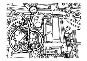
FUEL PRESSURE CHECK
-
Release fuel pressure.
-
Connect fuel hose for fuel pressure check (B) to fuel pressure gauge (A). Then, connect fuel hose for fuel pressure check to fuel tube adapter (SST: KV10120000) (D) with hose clamp (C).
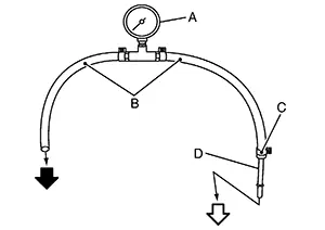

: To high pressure fuel pump

: To quick connector
CAUTION:
-
Use suitable fuel hose for fuel pressure check (genuine NISSAN fuel hose)
-
To avoid unnecessary force or tension to hose, use moderately long fuel hose for fuel pressure check.
-
Wipe off oil or dirt from hose insertion part using cloth moistened with gasoline.
-
Apply proper amount of gasoline on the hose insertion part.
-
Use NISSAN genuine hose clamp (part number: 16439 N4710 or 16439 N4710)
-
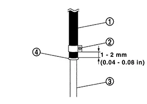
Install hose clamp to the hose end position within 1- 2 mm (0.04 - 0.08 in) and tighten hose clamp to the specified torque.
Tightening torque: 1 - 1.5 N┬Ęm (0.1 - 0.15 kgŌłÆm)
-
-
Disconnect quick connector and disconnect fuel feed hose from high pressure fuel pump. Refer to Exploded View.
CAUTION:
-
Make sure to release fuel pressure before removal of fuel line.
-
Do the following procedure in the place where ventilation is good without the combustible.
-
Prepare pans or saucers under the disconnected fuel line because the fuel may spill out. The fuel pressure cannot be completely released because this models do not have fuel return system.
-
Use fuel tube adapter (SST: KV10120000) and fuel pressure gauge (SST: ST19590000) to check fuel pressure.
-
-
Install fuel hose for fuel pressure check to high pressure fuel pump with hose clamp.
CAUTION:
-
Wipe off oil or dirt from hose insertion part using cloth moistened with gasoline.
-
Apply proper amount of gasoline on the hose insertion part.
-
Insert fuel hose for fuel pressure check
 until it touchesthe spool
  on high pressure fuel pump
  .
. -
Use NISSAN genuine hose clamp
 (part number: 16439ŌĆéN4710
or 16439ŌĆé40U00).
(part number: 16439ŌĆéN4710
or 16439ŌĆé40U00).
-
Install hose clamp to the hose end position within 1- 2 mm (0.04 - 0.08 in) and tighten hose clamp to the specified torque.
Tightening torque: 1 - 1.5 N┬Ęm (0.1 - 0.15 kgŌłÆm)
-
After connecting fuel hose for fuel pressure check, pull the hose with a force of approximately 100 N (approximately 10 kg, 22 lb) to confirm fuel sub tube does not come off.
-
-
Install fuel pressure check adapter to quick connector of fuel feed hose.
-
Turn ignition switch ON and check for fuel leakage.
-
Start engine and check for fuel leakage.
-
Stop the engine.
-
Turn ignition switch ON and read the indication of fuel pressure gauge (A).
At ignition switch ON
: Approximately 450 kPa (4.5 bar, 4.59 kg/cm2, 65.25 psi)
Is the inspection result normal?
YES >>INSPECTION END
NO >>GO TO 2.
-
-
CHECK FUEL HOSE
Check fuel hose for clogging.
Is the inspection result normal?
YES >>Repair or replace the malfunctioning part.
NO >>Replace fuel filter and fuel pump assembly. Refer to Removal and Installation.
How to Set Srt Code
Description
Description
OUTLINE
In order to set all SRTs, the self-diagnoses as in the ŌĆ£SRT ITEMŌĆØ table must have been performed at least once. Each diagnosis may require actual driving for a long period of time under various conditions.
SRT ITEM
The table below shows required self-diagnostic items to set the SRT to ŌĆ£CMPLTŌĆØ.
|
SRT item* (CONSULT indication) |
Required self-diagnostic items to set the SRT to ŌĆ£CMPLTŌĆØ |
Corresponding DTC No. |
|---|---|---|
|
FUEL SYSTEM |
Cylinder air-fuel inbalance |
P0171, P0172 |
|
CATALYST |
Three way catalyst function |
P0420 |
|
MISFIRE |
Cylinder function |
P0300, P0301, P0302, P0303, P0304 |
|
EVAP SYSTEM |
EVAP control system purge flow monitoring |
P0441 |
|
EVAP control system |
P0456 |
|
|
HO2S HTR |
Air fuel ratio (A/F) sensor 1 heater |
P0031, P0032, P0053 |
|
Heated oxygen sensor 2 heater |
P0037, P0038, P00D2 |
|
|
HO2S |
Air fuel ratio (A/F) sensor 1 |
P0130, P0131, P0132, P014C, P014D, P015A, P015B, P219A, P219C, P219D, P219E, P219F, P2096, P2097, P2237, P2238, P2239, P2251, P2252, P2253, P2297 |
|
Heated oxygen sensor 2 |
P0136, P0137, P0138, P0139, P2270, P2271, P2A01 |
|
|
EGR/VVT SYSTEM |
Intake/Exhaust valve timing control function |
P0011, P0012, P0014, P0016, P0401, P0402, P052A, P052B |
*: Though displayed on the CONSULT screen, ŌĆ£HO2S HTRŌĆØ is not SRT item.
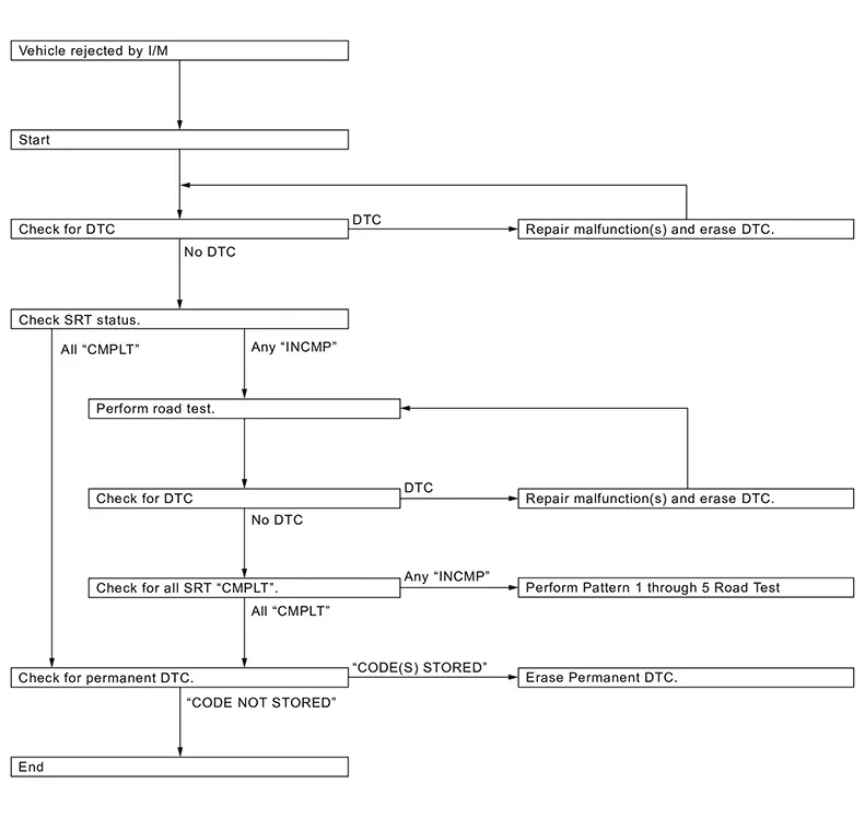
SRT SERVICE PROCEDURE
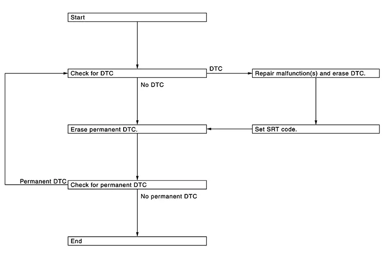
If a Nissan Sentra vehicle has failed the state emissions inspection due to one or more SRT items indicating ŌĆ£INCMPŌĆØ, review the flowchart diagnostic sequence, referring to the following flowchart.
Srt Set Driving Pattern
SRT Set Driving Pattern
CAUTION:
Always drive the vehicle in safe manner according to traffic conditions and obey all traffic laws.
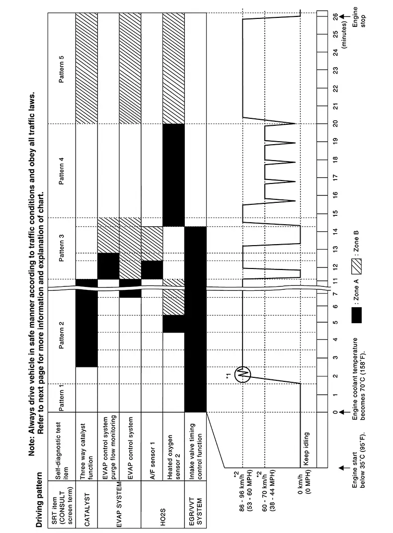 Note:
Note:
*1: Depress the accelerator pedal until Nissan Sentra vehicle speed is 90 km/h (56 MPH), then release the accelerator pedal and keep it released for more than 10 seconds. Depress the accelerator pedal until Nissan Sentra vehicle speed is 90 km/h(56 MPH) again.
*2: Checking the vehicle speed with GST is advised.
-
The time required for each diagnosis varies with road surface conditions, weather, altitude, individual driving habits, etc.
Zone A refers to the range where the time, required for the diagnosis under normal conditions*, is the shortest.
Zone B refers to the range where the diagnosis can still be performed if the diagnosis is not completed within zone A.
*: Normal conditions refer to the following:
-
Sea level
-
Flat road
-
Ambient air temperature: 20 - 30┬░C (68 - 86┬░F)
-
Diagnosis is performed as quickly as possible under normal conditions.
Under different conditions [For example: ambient air temperature other than 20 - 30┬░C (68 - 86┬░F)], diagnosis may also be performed.
-
"EGR/VVT SYSTEM" written in the figure is not applicable to the Nissan Sentra vehicle.
Work Procedure
Work Procedure
-
CHECK DTC
Check DTC.
Is any DTC detected?
YES >>Repair malfunction(s) and erase DTC. Refer to DTC Index.
NO >>GO TO 2.
-
CHECK SRT STATUS
With CONSULTSelect ŌĆ£SRT STATUSŌĆØ in ŌĆ£DTC & SRT CONFIRMATIONŌĆØ using CONSULT.
Without CONSULTPerform ŌĆ£SRT statusŌĆØ mode with Diagnosis Description.
 With GST
Select Service $01 with GST.
Is SRT code(s) set?
YES >>END
NO-1 >>
NO-2 >>With CONSULT: GO TO
3.Without CONSULT: GO TO
4. -
DTC CONFIRMATION PROCEDURE
-
Select ŌĆ£SRT WORK SUPPORTŌĆØ in ŌĆ£DTC & SRT CONFIRMATIONŌĆØ using CONSULT.
-
For SRT(s) that is not set, perform the corresponding ŌĆ£DTC CONFIRMATION PROCEDUREŌĆØ according to the ŌĆ£Performance PriorityŌĆØ in the ŌĆ£SRT ITEMŌĆØ table. Refer to Description.
-
Check DTC.
Is any DTC detected?
YES >>Repair malfunction(s) and erase DTC. Refer to DTC Index.
NO >>GO TO 9.
-
-
PERFORM ROAD TEST
-
Check the ŌĆ£Performance PriorityŌĆØ in the ŌĆ£SRT ITEMŌĆØ table. Refer to Description.
-
Perform the most efficient SRT set driving pattern to set the SRT properly. Refer to SRT Set Driving Pattern.
In order to set all SRTs, the SRT set driving pattern must be performed at least once.
GO TO 5.
-
-
PATTERN 1
-
Check the Nissan Sentra vehicle condition;
-
Engine coolant temperature is ŌłÆ10 to 35┬░C (14 to 95┬░F).
-
Fuel tank temperature is more than 0┬░C (32┬░F).
-
-
Start the engine.
-
Keep engine idling until the engine coolant temperature is greater than 70┬░C (158┬░F)
ECM terminal voltage is follows;
-
Engine coolant temperature
-
ŌłÆ10 to 35┬░C (14 to 95┬░F): 3.0 - 4.3 V
-
70┬░(158┬░F): Less than 1.4 V
-
GO TO 6.
-
-
PATTERN 2
-
Drive the Nissan Sentra vehicle. And depress the accelerator pedal until vehicle speed is 90 km/h (56 MPH), then release the accelerator pedal and keep it released for more than 10 seconds.
-
Depress the accelerator pedal until Nissan Sentra vehicle speed is 90 km/h (56 MPH) again
-
Checking the Nissan Sentra vehicle speed with GST is advised.
-
When steady-state driving is performed again even after it is interrupted, each diagnosis can be conducted. In this case, the time required for diagnosis may be extended.
GO TO 7.
-
-
PATTERN 3
-
Operate Nissan Sentra vehicle following the driving pattern shown in the figure.
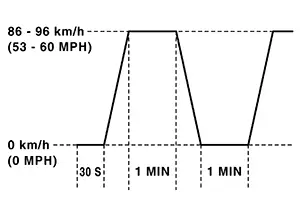
-
Release the accelerator pedal during deceleration of Nissan Sentra vehicle speed from 90 km/h (56 MPH) to 0 km/h (0 MPH).
GO TO 8.
-
-
PATTERN 4
-
Operate Nissan Sentra vehicle following the driving pattern shown in the figure.
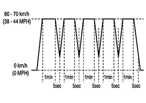
-
Drive the Nissan Sentra vehicle in a proper gear at 60 km/h (38 MPH) and maintain the speed.
-
Release the accelerator pedal fully at least 5 seconds.
-
Repeat the above two steps at least 5 times.
-
GO TO 9.
-
-
PATTERN 5
-
The accelerator pedal must be held very steady during steady-state driving.
-
If the accelerator pedal is moved, the test must be conducted again.
GO TO 10.
-
-
CHECK SRT STATUS
With CONSULTSelect ŌĆ£SRT STATUSŌĆØ in ŌĆ£DTC & SRT CONFIRMATIONŌĆØ using CONSULT.
WITHOUT CONSULTPerform ŌĆ£SRT statusŌĆØ mode with Diagnosis Description.
With GSTSelect Service $01 with GST.
Is SRT(s) set?
YES >>END
NO >>Perform this procedure again.
How to Erase Permanent Dtc
Work Procedure
Work Procedure
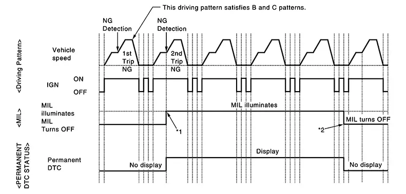
OUTLINE
When a DTC is stored in control module
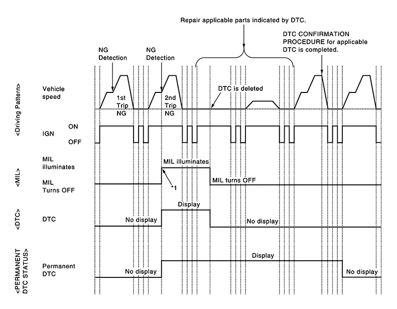
When a DTC is stored in control module and MIL is ON, a permanent DTC is erased with MIL shutoff if the same malfunction is not detected after performing the driving pattern for MIL shutoff three times in a raw.
|
*1: |
When the same malfunction is detected in two consecutive trips, MIL will illuminate. |
*2: |
MIL will turn off after Nissan Sentra vehicle is driven 3 times (driving pattern B) without any malfunctions. |
When a DTC is not stored in control module
The erasing method depends on a permanent DTC stored in control module. Refer to the following table.
Note:
If the applicable permanent DTC includes multiple groups, perform the procedure of Group B first. If the permanent DTC is not erased, perform the procedure of Group A.
├Ś: Applicable ŌĆö: Not applicable|
Group* |
Perform ŌĆ£DTC CONFIRMATION PROCEDUREŌĆØ for applicable DTCs. |
Driving pattern |
Reference |
|
|---|---|---|---|---|
|
B |
D |
|||
|
A |
├Ś |
ŌĆö |
ŌĆö |
Work Procedure (Group A) |
|
B |
ŌĆö |
├Ś |
├Ś |
Work Procedure (Group B) |
*: For group, refer to ŌĆ£DTC IndexŌĆØ of each control module.
PERMANENT DTC ITEM
For permanent DTC items, MIL turns ON. Refer to ŌĆ£DTC IndexŌĆØ of each control module.
PERMANENT DTC SERVICE PROCEDURE
Work Procedure (Group A)
|
*1: |
When the same malfunction is detected in two consecutive trips, MIL will illuminate. |
-
CHECK DTC
Check DTC.
Is any DTC detected?
YES >>Repair malfunction(s) and erase DTC. Refer to ŌĆ£DTC IndexŌĆØ of each control module.
NO >>GO TO 2.
-
CHECK PERMANENT DTC
With CONSULT-
Turn ignition switch OFF and wait at least 10 seconds.
-
Turn ignition switch ON.
-
Turn ignition switch OFF and wait at least 10 seconds.
-
Turn ignition switch ON.
-
Select ŌĆ£PERMANENT DTC STATUSŌĆØ mode with CONSULT.
With GST-
Turn ignition switch OFF and wait at least 10 seconds.
-
Turn ignition switch ON.
-
Turn ignition switch OFF and wait at least 10 seconds.
-
Turn ignition switch ON.
-
Select Service $0A with GST.
Is any permanent DTC detected?
YES >>GO TO 3.
NO >>END
-
-
PERFORM DTC CONFIRMATION PROCEDURE
Perform ŌĆ£DTC CONFIRMATION PROCEDUREŌĆØ for DTCs which are the same as permanent DTCs stored in control module.
>>GO TO 4.
-
CHECK PERMANENT DTC
With CONSULT-
Turn ignition switch OFF and wait at least 10 seconds.
-
Turn ignition switch ON.
-
Turn ignition switch OFF and wait at least 10 seconds.
-
Turn ignition switch ON.
-
Select ŌĆ£PERMANENT DTC STATUSŌĆØ mode with CONSULT.
With GST-
Turn ignition switch OFF and wait at least 10 seconds.
-
Turn ignition switch ON.
-
Turn ignition switch OFF and wait at least 10 seconds.
-
Turn ignition switch ON.
-
Select Service $0A with GST.
Is any permanent DTC detected?
YES >>GO TO 1.
NO >>END
-
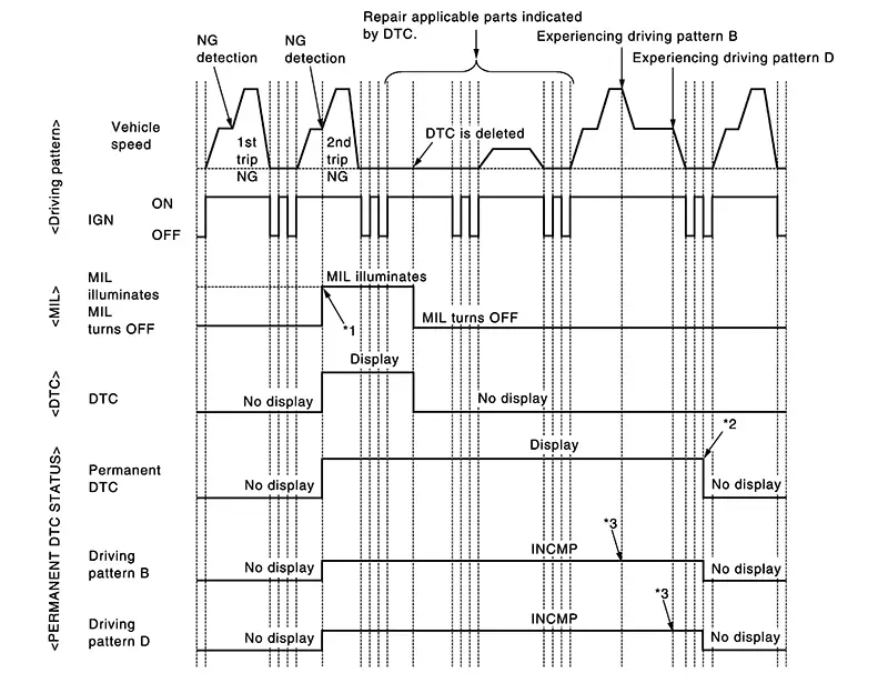
Work Procedure (Group B)
|
*1: |
When the same malfunction is detected in two consecutive trips, MIL will illuminate. |
*2: |
After experiencing driving pattern B and D, permanent DTC is erased. |
*3: |
Indication does not change unless the ignition switch is turned from ON to OFF twice even after experiencing driving pattern B or D. |
Drive the Nissan Sentra vehicle according to only driving patterns indicating ŌĆ£INCMPŌĆØ in driving patterns B and D on the ŌĆ£PERMANENT DTC STATUSŌĆØ screen.
-
CHECK DTC
Check DTC.
Is any DTC detected?
YES >>Repair malfunction(s) and erase DTC.
NO >>GO TO 2.
-
CHECK PERMANENT DTC
With CONSULT-
Turn ignition switch OFF and wait at least 10 seconds.
-
Turn ignition switch ON.
-
Turn ignition switch OFF and wait at least 10 seconds.
-
Turn ignition switch ON.
-
Select ŌĆ£PERMANENT DTC STATUSŌĆØ mode with CONSULT.
With GST-
Turn ignition switch OFF and wait at least 10 seconds.
-
Turn ignition switch ON.
-
Turn ignition switch OFF and wait at least 10 seconds.
-
Turn ignition switch ON.
-
Select Service $0A with GST.
Is any permanent DTC detected?
YES >>GO TO 3.
NO >>END
-
-
DRIVE DRIVING PATTERN B
CAUTION:
-
Always drive at a safe speed.
-
Never erase self-diagnosis results.
-
If self-diagnosis results are erased during the trip of driving pattern B or D, the counter of driving pattern B and D is reset.
With CONSULT-
Turn ignition switch ON.
-
Start engine and warm it up to normal operating temperature.
-
Use ŌĆ£PERMANENT DTC WORK SUPPORTŌĆØ mode with CONSULT to drive the Nissan Sentra vehicle according to driving pattern B. Refer to Diagnosis Description.
With GST-
Turn ignition switch ON.
-
Start engine and warm it up to normal operating temperature.
-
Drive the Nissan Sentra vehicle according to driving pattern B. Refer to Diagnosis Description.
GO TO 4.
-
-
CHECK PERMANENT DTC
With CONSULT-
Turn ignition switch OFF and wait at least 10 seconds.
-
Turn ignition switch ON.
-
Turn ignition switch OFF and wait at least 10 seconds.
-
Turn ignition switch ON.
-
Select ŌĆ£PERMANENT DTC STATUSŌĆØ mode with CONSULT.
With GST-
Turn ignition switch OFF and wait at least 10 seconds.
-
Turn ignition switch ON.
-
Turn ignition switch OFF and wait at least 10 seconds.
-
Turn ignition switch ON.
-
Select Service $0A with GST.
Is any permanent DTC detected?
YES >>GO TO 5.
NO >>END
-
-
DRIVE DRIVING PATTERN D
CAUTION:
-
Always drive at a safe speed.
-
Never erase self-diagnosis results.
-
If self-diagnosis results are erased during the trip of driving pattern B or D, the counter of driving pattern B and D is reset.
-
Drive the Nissan Sentra vehicle according to driving pattern D. Refer to Diagnosis Description.
GO TO 6.
-
-
CHECK PERMANENT DTC
With CONSULT-
Turn ignition switch OFF and wait at least 10 seconds.
-
Turn ignition switch ON.
-
Turn ignition switch OFF and wait at least 10 seconds.
-
Turn ignition switch ON.
-
Select ŌĆ£PERMANENT DTC STATUSŌĆØ mode with CONSULT.
With GST-
Turn ignition switch OFF and wait at least 10 seconds.
-
Turn ignition switch ON.
-
Turn ignition switch OFF and wait at least 10 seconds.
-
Turn ignition switch ON.
-
Select Service $0A with GST.
Is any permanent DTC detected?
YES >>GO TO 1.
NO >>END
-
Idle Air Volume Learning
Work Procedure
Work Procedure
Description
Idle Air Volume Learning is a function of ECM to learn the idle air volume that keeps engine idle speed within the specific range. It must be performed under the following conditions:
-
Each time electric throttle control actuator or ECM is replaced.
-
Idle speed or ignition timing is out of specification.
Work Procedure
Other materials:
Active Grille Shutter
Component Inspection
Component Inspection
CHECK ACTIVE GRILLE SHUTTER
With CONSULT
Start the engine.
Select ŌĆ£ACTIVE GRILLE
SHUTTERŌĆØ in ŌĆ£ACTIVE TESTŌĆØ mode of
ŌĆ£ENGINEŌĆØ using CONSULT.
...
Fuel Tank Temperature Sensor
Component Inspection
Component Inspection
CHECK FUEL TANK TEMPERATURE (FTT)
SENSOR
Turn ignition switch OFF.
Disconnect fuel level sensor unit and
fuel pump harness connector.
Remov ...
C1f6b-54 Camera Unit
Dtc Description
DTC Description
DTC DETECTION LOGIC
DTC
CONSULT screen terms
(Trouble diagnosis
content)
DTC detection
conditi ...