Nissan Sentra Service Manual: Unit removal and installation
Front suspension member
Exploded View
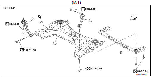
- Upper link
- Front suspension member
- Member stay
 Front
Front
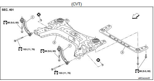
- Upper link
- Front suspension member
- Member stay
 Front
Front
Removal and Installation
REMOVAL
- Remove the front wheel and tire using power tool. Refer to WT-47, "Exploded View".
- Remove the front under cover and the engine under cover. Refer to EXT-30, "FRONT UNDER COVER : Removal and Installation".
- Disconnect the steering gear from the lower shaft. Refer to ST-12, "Removal and Installation".
- Disconnect the steering outer socket from the steering knuckle. Refer to ST-14, "Removal and Installation".
- Remove the nut and bolt from the lower ball joint. Disconnect the transverse link from the steering knuckle. Refer to FAX-8, "Exploded View".
- Remove the rear torque rod and the rear torque rod bracket.
- MRA8DE (M/T): Refer to EM-82, "M/T : Removal and Installation".
- MRA8DE (CVT): Refer to EM-86, "CVT : Removal and Installation".
- Disconnect the oxygen sensor. Refer to EX-5, "Removal and Installation".
- Disconnect the stabilizer connecting rod from the stabilizer bar. Refer to FSU-12, "Exploded View".
- Set a suitable jack under front suspension member.
CAUTION:
- At this step, the suitable jack must be set only for supporting the removal procedure. For details on jacking up the vehicle, refer to GI-31, "Garage Jack and Safety Stand and 2-Pole Lift".
- Do not damage the front suspension member with the suitable jack.
- Remove the lower bolts from the upper links.
- Remove the bolts and the member stay.
- Remove the front suspension member bolts.
- Gradually lower the suitable jack to remove the front suspension member from the vehicle.
CAUTION:
Make sure the front suspension member is stable when using the suitable jack.
- If replacing the front suspension member, perform the following procedures:
- Remove the steering gear. Refer to ST-14, "Exploded View".
- Remove the transverse links. Refer to FSU-10, "Exploded View".
- Remove the stabilizer bar, the stabilizer clamps, and the stabilizer bushings. Refer to FSU-12, "Exploded View".
- Remove the oxygen sensor bracket. Refer to EX-5, "Exploded View".
- Inspect the components. Refer to FSU-18, "Inspection".
INSTALLATION
Installation is in the reverse order of removal.
CAUTION:
Do not reuse the transverse link nuts.
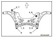
- Install the member stay bolts, the upper link bolts, and the front suspension member bolts in the order of 1 to 10 as shown (if equipped with the 6M/T).
Temporary tightening : 1 → 2→ 3 → 4
Final tightening (Specified torque) : 5 → 6 → 7 → 8 → 9 → 10
 : Front
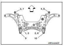
- Install the member stay bolts, the upper link bolts, and the front suspension member bolts in the order of 1 to 10 as shown (if equipped with the CVT).
Temporary tightening : 1 → 2→ 3 → 4
Final tightening (Specified torque) : 5 → 6 → 7 → 8 → 9 → 10
 : Front
- Perform the final tightening of the nuts and bolts under unladen conditions with the tires on level ground.
- Complete the inspection. Refer to FSU-18, "Inspection".
Inspection
INSPECTION AFTER REMOVAL
Check the front suspension member for cracks, wear or damage. Replace components if necessary.
INSPECTION AFTER INSTALLATION
- Check the wheel sensor harness to be sure the connectors are fully seated.
- Check the neutral position of the steering angle sensor. Refer to BRC-54, "Work Procedure".
- Check the wheel alignment. Refer to FSU-6, "Inspection".
 Steering knuckle
Exploded View
Steering knuckle
Splash guard
Wheel stud
Wheel hub and bearing
Disc brake rotor
Wheel hub lock nut
Nut retainer
Cotter pin
Removal and Installation
REMOVAL
...
 Unit disassembly and assembly
Front coil spring and strut
Exploded View
Piston rod lock nut
Strut mount insulator
Strut mount bearing
Bound bumper
Coil spring
Lower rubber seat
Strut
Steering knuckle
Fro ...
Other materials:
M&A branch line circuit
Diagnosis procedure
1.Check connector
Turn the ignition switch off.
Disconnect the battery cable from the negative terminal.
Check the terminals and connectors of the combination meter for damage,
bend and loose connection
(unit side and connector side).
Is the inspection result nor ...
Washer motor circuit
Diagnosis Procedure
Regarding Wiring Diagram information, refer to WW-24, "Wiring Diagram - With
Intelligent Key" or WW-29,
"Wiring Diagram - Without Intelligent Key".
1. Check front washer motor fuse
Turn the ignition switch OFF.
Check that the following fuse is not b ...
Precaution
Precaution for supplemental restraint system (srs) "air bag" and "seat
belt pre-tensioner"
The supplemental restraint system such as “air bag” and “seat belt pre-tensioner”,
used along
with a front seat belt, helps to reduce the risk or severity of injur ...
