Nissan Sentra Service Manual: System
Body control system
Body control system : system description
OUTLINE
- BCM (Body Control Module) controls the various electrical components. It inputs the information required to the control from CAN communication and the signal received from each switch and sensor.
- BCM has combination switch reading function for reading the operation
status of combination switches (light,
turn signal, wiper and washer) in addition to a function for controlling the
operation of various electrical components.
It also has the signal transmission function as the passed point of signal and the power saving control function that reduces the power consumption with the ignition switch OFF.
- BCM is equipped with the diagnosis function that performs the diagnosis with CONSULT and various settings.
BCM CONTROL FUNCTION LIST
Combination switch reading system
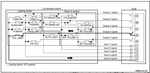
Combination switch reading system : system diagram
Combination switch reading system : system description
OUTLINE
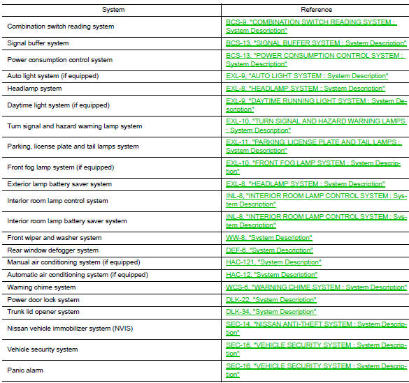
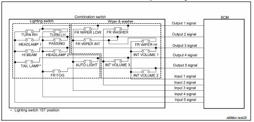
- BCM reads the status of the combination switch (light, turn signal, wiper and washer) and recognizes the status of each switch.
- BCM has a combination of 5 output terminals (OUTPUT 1 - 5) and 5 input terminals (INPUT 1 - 5). It reads a maximum of 20 switch states.
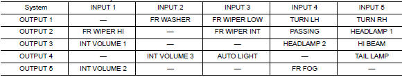
COMBINATION SWITCH MATRIX
Combination switch circuit
Combination switch INPUT-OUTPUT system list
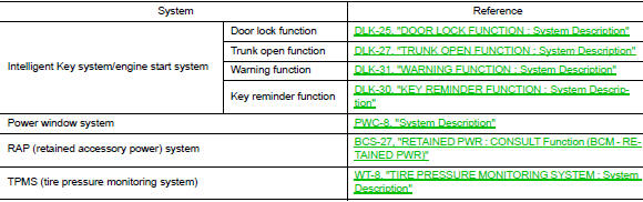
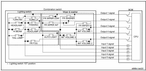
COMBINATION SWITCH READING FUNCTION
Description
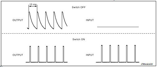
- BCM reads the status of the combination switch at 10 ms intervals normally.
NOTE:
BCM reads the status of the combination switch at 60 ms intervals when BCM is controlled at low power consumption control mode.
BCM operates as follows and judges the status of the combination switch.
- It operates the transistor on OUTPUT side in the following order: OUTPUT 1 → 2 → 3 → 4 → 5, and outputs voltage waveform.
- The voltage waveform of OUTPUT corresponding to the formed circuit is input into the interface on INPUT side if any (1 or more) switches are ON.
- It reads this change of the voltage as the status signal of the combination switch.
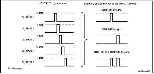
Operation Example
In the following operation example, the combination of the status signals of the combination switch is replaced as follows: INPUT 1 - 5 to “1 - 5” and OUTPUT 1 - 5 to “A - E”.
Example 1: When a switch (TAIL LAMP) is turned ON
- The circuit between OUTPUT 4 and INPUT 5 is formed when the TAIL LAMP switch is turned ON.
- BCM detects the combination switch status signal “5D” when the signal of OUTPUT 4 is input to INPUT 5.
- BCM judges that the TAIL LAMP switch is ON when the signal “5D” is detected.
Example 2: When some switches (TURN RH, TAIL LAMP) are turned ON
- The circuits between OUTPUT 1 and INPUT 5 and between OUTPUT 4 and INPUT 5 are formed when the TURN RH switch and TAIL LAMP switch are turned ON.
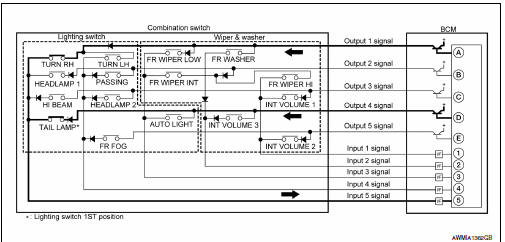
- BCM detects the combination switch status signal “5AD” when the signals of OUTPUT 1 and OUTPUT 4 are input to INPUT 5.
- BCM judges that the TURN RH switch and TAIL LAMP switch are ON when the signal “5AD” is detected.
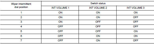
Wiper intermittent dial position
Bcm judges the wiper intermittent dial 1 - 7 by the status of int volume 1, 2 and 3 switches.
Note:
For details of wiper intermittent dial position, refer to WW-8, "System Description".
Signal buffer system
Signal buffer system : system diagram
Signal buffer system : system description
Outline
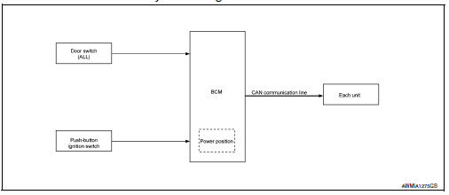
Bcm has the signal transmission function that outputs/transmits each input/received signal to each unit.
Signal transmission function list
| Signal name | Input | Output | Description |
|
Engine switch (push switch) | IPDM E/R (CAN) | Inputs the push-button ignition switch (push switch) signal and transmits the ignition switch status judged with BCM via CAN communication. |
| Door switch signal | Any door switch |
|
Inputs the door switch signal and transmits it via can communication. |
Power consumption control system
POWER CONSUMPTION CONTROL SYSTEM : System Diagram
Power consumption control system : system description
Outline
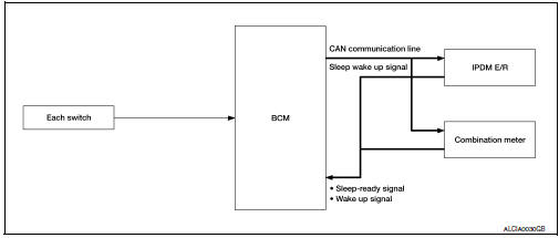
- Bcm incorporates a power saving control function that reduces the power consumption according to the vehicle status.
- Bcm switches the status (control mode) by itself with the power saving control function. It performs the sleep request to each unit (ipdm e/r and combination meter) that operates with the ignition switch off.
Normal mode (wake-up)
- Can communication is normally performed with other units
- Each control with BCM is operating properly
Can communication sleep mode (can sleep)
- Can transmission is stopped
- Control with bcm only is operating
Low power consumption mode (bcm sleep)
- Low power consumption control is active
- CAN transmission is stopped
Low power consumption control with bcm
BCM reduces the power consumption with the following operation in the low power consumption mode.
- The reading interval of each switch changes from 10 ms interval to 60 ms interval.
Sleep mode activation
- Bcm receives the sleep-ready signal (ready) from ipdm e/r and combination meter via can communication.
- BCM transmits the sleep wake up signal (sleep) to each unit when all of the CAN sleep conditions are fulfilled.
- Each unit stops the transmission of can communication with the sleep wakeup signal. Bcm is in can communication sleep mode.
- Bcm is in the low power consumption mode and performs the low power consumption control when all of the bcm sleep conditions are fulfilled with can sleep condition.
Sleep condition
| Can sleep condition | Bcm sleep condition |
|
|
Wake-up operation
- Bcm changes from the low power consumption mode to the can communication sleep mode when the any of the bcm wake-up conditions are fulfilled. Only the control with bcm is activated.
- BCM transmits the sleep wake up signal (wake up) to each unit when any of the CAN wake-up conditions are fulfilled. It changes from the low power consumption mode or the CAN communication sleep mode to the normal mode.
- Each unit starts the transmission of CAN communication with the sleep wake up signal. In addition, the combination meter transmits the wake up signal to BCM via CAN communication to report the CAN communication start.
| Bcm wake-up condition | Can wake-up condition |
|
|
 System description
Component parts
Body control system
Body control system : component parts location
BCM (view with instrument panel removed)
Combination switch reading system
Combination switch reading s ...
 Diagnosis system (bcm)
Common item
COMMON ITEM : CONSULT Function (BCM - COMMON ITEM)
Application item
Consult performs the following functions via can communication with bcm.
Direct diagnostic mode
Descriptio ...
Other materials:
C1113, C1145, C1146 Yaw rate/side/decel G Sensor
DTC Logic
DTC DETECTION LOGIC
DTC
Display Item
Malfunction detected condition
Possible causes
C1113
G SENSOR
When a malfunction is detected in longitunal G sensor
signal.
ABS actuator and electric unit (control unit)
C1145
YAW RATE ...
Application Download
Once connected, the NissanConnect™ App will
search your phone to determine which compatible
applications are currently installed. The user
will then choose which apps they want to bring
into their vehicle from the list of apps within the
“Manage My Apps” section of the NissanConnect
™ ...
Continuously Variable Transmission (CVT) (if so equipped)
The ignition lock is designed so that the ignition
switch cannot be turned to the LOCK position
until the shift lever is moved to the P (Park)
position.
When moving the ignition switch to the
LOCK position, make sure the shift lever is in
the P (Park) position.
When removing the key ...
