Nissan Sentra Service Manual: Structure and operation
Positive Crankcase Ventilation
This system returns blow-by gas to the intake manifold.
The positive crankcase ventilation (PCV) valve is provided to conduct crankcase blow-by gas to the intake manifold.
During partial throttle operation of the engine, the intake manifold sucks the blow-by gas through the PCV valve.
Normally, the capacity of the valve is sufficient to handle any blow-by and a small amount of ventilating air.
The ventilating air is then drawn from the air inlet tubes into the crankcase. In this process the air passes through the hose connecting air inlet tubes to rocker cover.
Under full-throttle condition, the manifold vacuum is insufficient to draw the blow-by flow through the valve.
The flow goes through the hose connection in the reverse direction.
On vehicles with an excessively high blow-by, the valve does not meet the requirement. This is because some of the flow will go through the hose connection to the air inlet tubes under all conditions.
On Board Refueling Vapor Recovery (ORVR)
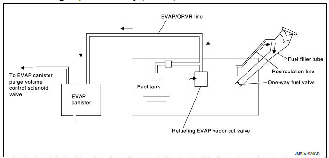
From the beginning of refueling, the air and vapor inside the fuel tank go through refueling EVAP vapor cut valve and EVAP/ORVR line to the EVAP canister. The vapor is absorbed by the EVAP canister and the air is released to the atmosphere.
When the refueling has reached the full level of the fuel tank, the refueling EVAP vapor cut valve is closed and refueling is stopped because of auto shut-off. The vapor which was absorbed by the EVAP canister is purged during driving.
WARNING:
- When conducting inspections below, be sure to observe the following:
- Put a “CAUTION: FLAMMABLE” sign in workshop.
- Do not smoke while servicing fuel system. Keep open flames and sparks away from work area.
- Be sure to furnish the workshop with a CO2 fire extinguisher.
CAUTION:
- Before removing fuel line parts, carry out the following procedures:
- Put drained fuel in an explosion-proof container and put lid on securely.
- Release fuel pressure from fuel line. Refer to EC-481, "Inspection".
- Disconnect battery ground cable.
- Always replace O-ring when the fuel gauge retainer is removed.
- Do not kink or twist hose and tube when they are installed.
- Do not tighten hose and clamps excessively to avoid damaging hoses.
- After installation, run engine and check for fuel leaks at connection.
- Do not attempt to top off the fuel tank after the fuel pump nozzle
shuts off automatically.
Continued refueling may cause fuel overflow, resulting in fuel spray and possibly a fire.
 Component parts
Engine control system
ENGINE CONTROL SYSTEM :Component Parts Location
Engine room compartment
No.
Component
Function
1
IPDM E/R
IPDM E/R control the internal relays ...
 System
...
Other materials:
System description
Component parts
Component parts location
Ipdm e/r
System
Relay control system
Relay control system : system diagram
Relay control system : system description
Description
IPDM E/R activates the internal control circuit to perform the relay ON-OFF
control according to the input ...
Checking bulbs
With all doors closed, apply the parking brake
and place the ignition switch in the ON position
without starting the engine. The following lights
will come on:
If equipped, the following lights come on briefly
and then go off:
If any light fails to come on, it may indicate
an open circuit ...
Structure and operation
TRANSAXLE
TRANSAXLE : Cross-Sectional View
Converter housing
Oil pump
Counter drive gear
Control valve
Oil pan
Primary pulley
Steel belt
Secondary pulley
Planetary gear (auxiliary gearbox)
Side cover
Transaxle case
Differential case
Final gear
Reduction gear
Cou ...
