Nissan Sentra Service Manual: Shift lock system
Component Function Check
1.CHECK SHIFT LOCK OPERATION (PART 1)
- Turn ignition switch ON.
- Shift the selector lever to park “P” position.
- Attempt to shift the selector lever to any other position with the brake pedal released.
Can the selector lever be shifted to any other position? YES >> Go to TM-241, "Diagnosis Procedure".
NO >> GO TO 2.
2.CHECK SHIFT LOCK OPERATION (PART 2)
Attempt to shift the selector lever to any other position with the brake pedal depressed.
Can the selector lever be shifted to any other position? YES >> Inspection End.
NO >> Go to TM-241, "Diagnosis Procedure".
Diagnosis Procedure
Regarding Wiring Diagram information, refer to TM-136, "Wiring Diagram".
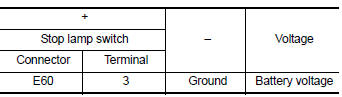
1.CHECK POWER SOURCE (PART 1)
- Turn ignition switch OFF.
- Disconnect stop lamp switch connector.
- Turn ignition switch ON.
- Check the voltage between the stop lamp switch harness connector terminal and ground.
Is the inspection result normal? YES >> GO TO 2.
NO >> GO TO 9.
2.CHECK STOP LAMP SWITCH MOUNTING POSITION
Check stop lamp switch mounting position. Refer to BR-15, "Adjustment".
Is the inspection result normal? YES >> GO TO 3.
NO >> Adjust stop lamp switch mounting position.
3.CHECK STOP LAMP SWITCH
Check stop lamp switch. Refer to TM-243, "Component Inspection (Stop Lamp Switch)".
Is the inspection result normal? YES >> GO TO 4.
NO >> Repair or replace stop lamp switch.
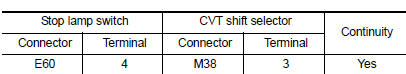
4.CHECK CIRCUIT BETWEEN STOP LAMP SWITCH AND CVT SHIFT SELECTOR (PART 1)
- Disconnect CVT shift selector connector
- Check the continuity between the stop lamp switch harness connector terminal and the CVT shift selector harness connector terminal.
 Is the inspection
result normal?
YES >> GO TO 5.
NO >> Repair or replace damaged parts.
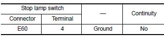
5.CHECK CIRCUIT BETWEEN STOP LAMP SWITCH AND CVT SHIFT SELECTOR (PART 2)
Check the continuity between the stop lamp switch harness connector terminal and ground.
 Is the inspection
result normal?
YES >> GO TO 6.
NO >> Repair or replace damaged parts.
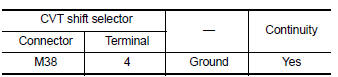
6.CHECK GROUND CIRCUIT
Check the continuity between the CVT shift selector harness connector terminal and ground.
 Is the inspection
result normal?
YES >> GO TO 7.
NO >> Repair or replace damaged parts.
7.CHECK PART POSITION SWITCH
- Disconnect park position switch connector.
- Check park position switch. Refer to TM-243, "Component Inspection (Park Position Switch)".
Is the inspection result normal? YES >> GO TO 8.
NO >> Repair or replace damaged parts.
8.CHECK SHIFT LOCK SOLENOID
- Disconnect shift lock solenoid connector.
- Check shift lock solenoid. Refer to TM-243, "Component Inspection (Shift Lock Solenoid)".
Is the inspection result normal? YES >> GO TO 9.
NO >> Repair or replace damaged parts.
9.DETECT MALFUNCTIONING ITEM
Check the following items:
- Open or short circuit of the harness between ignition switch and stop lamp switch connector. Refer to PG-20, "Wiring Diagram — Ignition Power Supply —"
- Ignition switch
- 10A fuse [No.5, fuse block (J/B)]. Refer to PG-47, "Terminal Arrangement".
Is the inspection result normal? YES >> Check intermittent incident. Refer to GI-39, "Intermittent Incident".
NO >> Repair or replace damaged parts.
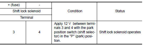
Component Inspection (Shift Lock Solenoid)
1.CHECK SHIFT LOCK SOLENOID
Apply voltage to terminals of shift lock solenoid and park position switch (shift selector) connector and check that shift lock solenoid is activated.
CAUTION:
- Connect a fuse between the terminals when applying voltage.
- Never cause shorting between terminals.
 Is the inspection
result normal?
YES >> Inspection End.
NO >> Replace CVT shift selector. Refer to TM-253, "Removal and Installation".
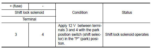
Component Inspection (Park Position Switch)
1.CHECK PARK POSITION SWITCH (SHIFT SELECTOR)
Apply voltage to terminals of shift lock solenoid and park position switch (shift selector) connector and check that shift lock solenoid is activated.
CAUTION:
- Connect a fuse between the terminals when applying voltage.
- Never cause shorting between terminals.
 Is the inspection
result normal?
YES >> Inspection End.
NO >> Replace CVT shift selector. Refer to TM-253, "Removal and Installation".
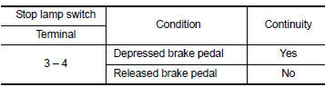
Component Inspection (Stop Lamp Switch)
1.CHECK STOP LAMP SWITCH
Check the continuity between the stop lamp switch connector terminals.
 Is the inspection
result normal?
YES >> Inspection End.
NO >> Replace stop lamp switch. Refer to BR-22, "Exploded View".
 Shift position indicator circuit
Component Parts Function Inspection
1.CHECK SHIFT POSITION INDICATOR
Start the engine.
Shift selector lever.
Check that the selector lever position and the shift position indicator
on the ...
 Symptom diagnosis
CVT CONTROL SYSTEM
Symptom Table
The diagnosis item number indicates the order of check. Start checking in the
order from 1.
...
Other materials:
Power supply and ground circuit
Av control unit
Av control unit : diagnosis procedure
Regarding wiring diagram information, refer to av-331, "wiring diagram".
1.Check fuse
Check that the following fuses are not blown.
Are the fuses blown?
Yes >> replace the blown fuse after repairing the affected circuit. ...
Unbalance steering wheel turning force and return between right
and left
Description
Unbalance steering wheel turning force and return between right
and left.
Diagnosis Procedure
1.CHECK THE ILLUMINATION OF THE EPS WARNING LAMP
Check the EPS warning lamp while engine is running.
Does the EPS warning lamp turn OFF?
YES >> GO TO 2.
NO >> Refer to S ...
Small children
Children that are over 1 year old and weigh at
least 20 lbs (9 kg) should remain in a rear-facing
child restraint as long as possible up to the height
or weight limit of the child restraint. Children who
outgrow the height or weight limit of the rearfacing
child restraint and are at least 1 yea ...
