Nissan Sentra Service Manual: Rear shock absorber
Exploded View
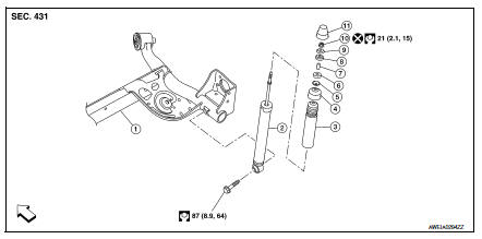
- Rear suspension beam
- Shock absorber
- Bound bumper
- Bound bumper cover
- Washer
- Bushing
- Distance tube
- Bushing
- Washer
- Piston rod lock nut
- Cap
 Front
Front
Removal and Installation
REMOVAL
- Remove the rear shock tower access flap.
- Remove the cap from the rear shock absorber.
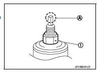
- Remove the piston rod lock nut (1).
NOTE:
To loosen the piston rod lock nut, hold the tip (A) of the piston rod.
- Remove the washer and the bushing.
- Set a suitable jack under the rear suspension beam.
CAUTION:
- At this step, the jack must be set only for supporting the removal procedure. For details on jacking up the vehicle, refer to GI-31, "Garage Jack and Safety Stand and 2-Pole Lift".
- Do not damage the rear suspension beam with the jack.
- Make sure the rear suspension beam is stable when using the jack.
- Remove the lower shock absorber bolt.
- Remove the rear shock absorber.
- Remove the bushing, the distance tube, the washer, the bound bumper cover, and the bound bumper from the shock absorber.
- Inspect the components. Refer to RSU-10, "Inspection".
INSTALLATION
Installation is in the reverse order of removal.
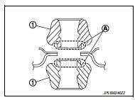
- To install the bushings (1), securely insert the protrusion (A) into the hole in the vehicle body.
- Install the washer (1) in the direction shown.
 : Bushing side
- Perform the final tightening of the bolts and nuts under unladen conditions with the tires on level ground.
- Hold the tip (A) of the piston rod. Tighten the piston rod lock nut (1) to the specification.
CAUTION:
Do not reuse the piston rod lock nut.
- When installing the cap, securely engage the cap groove (A) with the flange on the vehicle body.
- After replacing the shock absorber, always follow the disposal procedure
to discard the old shock absorber.
Refer to RSU-10, "Disposal".
Inspection
INSPECTION AFTER REMOVAL
Shock Absorber
Check the following items and replace the parts if necessary.
- Check the shock absorber for oil leaks, deformation, cracks, and other damage.
- Check the piston rod for damage, uneven wear, and distortion.
Bound Bumper, Bushing
Check for cracks and damage. Replace the parts if necessary.
Washer, Bound Bumper Cover, Distance Tube
- Check for cracks and damage. Replace the parts if necessary.
Disposal
- Set the shock absorber horizontally with the piston rod fully extended.
- Drill a 2 – 3 mm (0.08 – 0.12 in) hole at the position (

) from the top as shown to release gas gradually.
CAUTION:
- Wear eye protection (safety glasses).
- Wear gloves.
- Be careful with metal chips or oil blown out by the compressed gas.
NOTE:
- Drill vertically in this direction (

). - Drill directly to the outer tube avoiding brackets.
- The gas is clear, colorless, odorless, and harmless.
(A) : 20 – 30 mm (0.79 – 1.18 in)
- Position the drilled hole downward and drain oil by moving the piston rod several times.
CAUTION:
Dispose of drained oil according to the law and local regulations.

 Coil spring
Exploded View
Upper rubber seat
Coil spring
Lower rubber seat
Rear suspension beam
Front
Removal and Installation
REMOVAL
Set a suitable jack under the rear suspension beam.
...
Other materials:
The door open warning continues displaying, or does not display
Description
The door ajar warning is displayed even though all of the doors are
closed.
The door ajar warning is not displayed even though a door is ajar.
Diagnosis procedure
1.Check bcm input signal
Check the bcm input signal. Refer to dlk-102, "component function check"
( ...
Periodic maintenance
M/T OIL
Inspection
OIL LEAKAGE
Make sure that gear oil is not leaking from transaxle or around it.
OIL LEVEL
Remove filler plug (1) and gasket from transaxle case.
Check the oil level from filler plug mounting hole as shown.
CAUTION:
Do not start engine while checking oil level.
Se ...
FM radio reception
Range: FM range is normally limited to 25 – 30 mi
(40 – 48 km), with monaural (single channel) FM
having slightly more range than stereo FM. External
influences may sometimes interfere with FM
station reception even if the FM station is within
25 mi (40 km). The strength of the FM signal is ...
