Nissan Sentra Service Manual: Push-button ignition switch illumination circuit
Description
Provides the power supply and the ground to control the push-button ignition switch illumination.
Component function check
1.Check push-button ignition switch illumination operation
 Consult active test
- Turn the ignition switch ON.
- Select engine sw illumi of bcm (intelligent key) active test item.
- With operating the test items, check that the push-button ignition switch illumination turns ON/OFF.
On : push-button ignition switch illumination on
Off : push-button ignition switch illumination off
Does the push-button ignition switch illumination turn on/off? Yes >> push-button ignition switch illumination circuit is normal.
No >> refer to inl-49, "diagnosis procedure".
Diagnosis procedure
Regarding wiring diagram information, refer to inl-26, "wiring diagram".
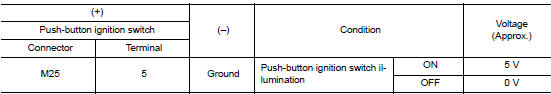
1.Check push-button ignition switch illumination power supply output
- Turn the ignition switch OFF
- Disconnect push-button ignition switch connector.
- Check voltage between push-button ignition switch harness connector and ground.
Is the inspection result normal? Yes >> go to 4.
No >> go to 2.
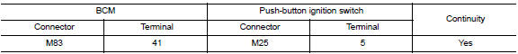
2.Check push-button ignition switch illumination power supply open circuit
- Disconnect bcm connector.
- Check continuity between bcm harness connector and the push-button ignition switch harness connector.
Is the inspection result normal? Yes >> go to 3.
No >> repair or replace harness or connector.
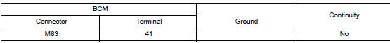
3.Check push-button ignition switch illumination power supply short circuit
Check continuity between bcm harness connector and ground.
Is the inspection result normal? YES >> Replace BCM. Refer to BCS-73, "Removal and Installation" (with Intelligent Key), BCS-126, "Removal and Installation" (without Intelligent Key).
NO >> Repair or replace harness or connector.
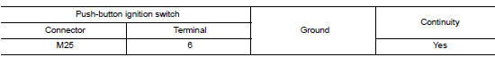
4.Check push-button ignition switch illumination ground circuit
Check continuity between push-button ignition switch harness connector and ground.
Is the inspection result normal? Yes >> replace push-button ignition switch. Refer to sec-136, "removal and installation".
No >> repair or replace harness or connector.
 Trunk room lamp circuit
Description
Controls the trunk room lamp (ground side) to turn the trunk room lamp on and
off.
Diagnosis Procedure
Regarding wiring diagram information, refer to inl-17, "wiring diagram" ...
 Symptom diagnosis
Interior lighting system symptoms
Symptom Table
Caution:
Perform the self-diagnosis with consult before the symptom diagnosis.
Perform the trouble diagnosis
if any dtc is detected.
...
Other materials:
Precaution
Precaution for Supplemental Restraint System (SRS) "AIR BAG" and "SEAT
BELT PRE-TENSIONER"
The Supplemental Restraint System such as “AIR BAG” and “SEAT BELT PRE-TENSIONER”,
used along
with a front seat belt, helps to reduce the risk or severity of inju ...
Ecu diagnosis information
Ipdm e/r (intelligent power distribution module engine room)
Reference Value
Values on the diagnosis tool
Terminal layout
Physical values
Fail-safe
Can communication control
When CAN communication with ECM and BCM is impossible, IPDM E/R performs
fail-safe ...
Water pump
Exploded View
Gasket
Water pump
WARNING:
Do not remove the radiator cap when the engine is hot. Serious burns
could occur from high-pressure
engine coolant escaping from the radiator. Wrap a thick cloth around the cap.
Slowly push down and
turn it a quarter turn to allow built-up ...
