Nissan Sentra Service Manual: Power supply and ground circuit
Diagnosis Procedure
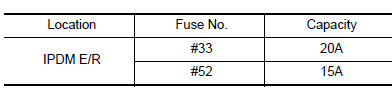
1.CHECK FUSE
Check that the following fuse is not fusing.
Is the fuse fusing? YES >> Replace the fuse after repairing the applicable circuit.
NO >> GO TO 2.
2.CHECK GROUND CONNECTION
- Turn ignition switch OFF
- Check ground connection E9 and E15. Refer to GI-42, "Circuit Inspection".
Is the inspection result normal? YES >> GO TO 3.
NO >> Repair or replace ground connection.
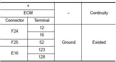
3.CHECK ECM GROUND CIRCUIT
- Disconnect ECM harness connectors.
- Check the continuity between ECM harness connector and ground.
Is the inspection result normal? YES >> GO TO 4.
NO >> Repair or replace error-detected parts.
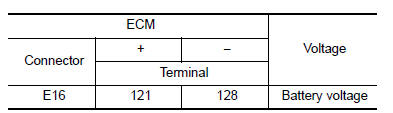
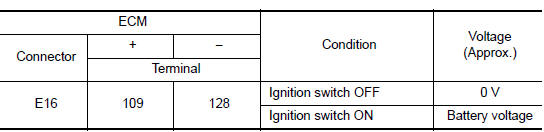
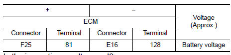
4.CHECK ECM POWER SUPPLY (MAIN)-1
- Reconnect ECM harness connector.
- Turn ignition switch ON.
- Check the voltage between ECM harness connector terminals.
Is the inspection result normal? YES >> GO TO 5.
NO >> GO TO 6.
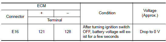
5.CHECK ECM POWER SUPPLY (MAIN)-2
- Turn ignition switch OFF and wait at least 10 seconds.
- Check the voltage between ECM harness connector terminals as per the following.
Is the inspection result normal? YES >> GO TO 9.
NO >> GO TO 7.
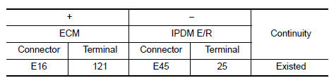
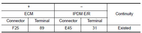
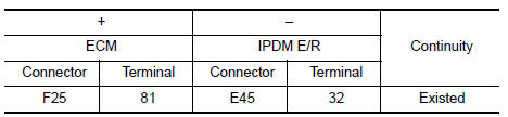
6.CHECK ECM POWER SUPPLY (MAIN) CIRCUIT
- Turn ignition switch OFF.
- Disconnect ECM harness connectors.
- Disconnect IPDM E/R harness connector.
- Check the continuity between ECM harness connector and IPDM E/R harness connector.
- Also check harness for short to ground.
Is the inspection result normal? YES >> Perform the trouble diagnosis for power supply circuit.
NO >> Repair or replace error-detected parts.
7.CHECK ECM RELAY CONTROL SIGNAL
Check the voltage between ECM harness connector terminals as per the following.

Is the inspection result normal? YES >> Check Intermittent incident. Refer to GI-39, "Intermittent Incident".
NO >> GO TO 8.
8.CHECK ECM RELAY CONTROL SIGNAL CIRCUIT
- Turn ignition switch OFF
- Disconnect ECM harness connector.
- Disconnect IPDM E/R harness connector
- Check the continuity between ECM harness connector and IPDM E/R harness connector.
- Also check harness for short to ground and to power.
Is the inspection result normal? YES >> Replace IPDM E/R. Refer to PCS-58, "Removal and Installation" (with intelligent key), PCS-58, "Removal and Installation" (without intelligent key).
NO >> Repair or replace error-detected parts.
9.CHECK IGNITION SWITCH SIGNAL
- Turn ignition switch ON.
- Check the voltage between ECM harness connector terminals.
Is the inspection result normal? YES >> GO TO 11.
NO >> GO TO 10.
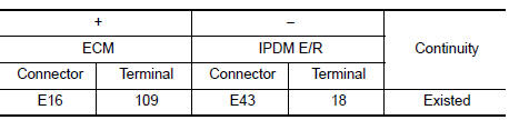
10.CHECK IGNITION SWITCH SIGNAL CIRCUIT
- Turn ignition switch OFF.
- Disconnect ECM harness connector.
- Disconnect IPDM E/R harness connector.
- Check the continuity between ECM harness connector and IPDM E/R harness connector.
- Also check harness for short to ground and to power.
Is the inspection result normal? YES >> Perform the trouble diagnosis for power supply circuit.
NO >> Repair or replace error-detected parts.
11.CHECK ECM POWER SUPPLY (BACK-UP)
Check the voltage between ECM harness connector terminals.
Is the inspection result normal? YES >> Check Intermittent Incident. Refer to GI-39, "Intermittent Incident".
NO >> GO TO 12.
12.CHECK ECM POWER SUPPLY (BACK-UP) CIRCUIT
- Turn ignition switch OFF.
- Disconnect ECM harness connector.
- Disconnect IPDM E/R harness connector.
- Check the continuity between ECM harness connector and IPDM E/R harness connector.
- Also check harness for short to ground.
Is the inspection result normal? YES >> Perform the trouble diagnosis for power supply circuit.
NO >> Repair or replace error-detected parts.
 Trouble diagnosis - specification
value
Trouble diagnosis - specification
value
Description
The specification (SP) value indicates the tolerance of the value that is
displayed in “SPEC” of “DATA MONITOR”
mode of CONSULT during normal operation of the Engin ...
 U0101 can comm circuit
Description
CAN (Controller Area Network) is a serial communication line for real time
application. It is an on-vehicle multiplex
communication line with high data communication speed and excellen ...
Other materials:
U1010 Control unit (CAN)
Description
Air bag diagnosis sensor performs self-tests on key ON. If CAN communication
failure within control unit is
detected, DTC is set.
DTC Logic
DTC DETECTION LOGIC
CONSULT name
DTC
DTC detecting condition
Repair order
CAN CONTROL UNIT FAILURE
U1010
CAN ...
Warning signals
To help prevent the vehicle from moving unexpectedly
by erroneous operation of the Intelligent
Key or to help prevent the vehicle from being
stolen, a chime or buzzer sounds from inside and
outside the vehicle and a warning light comes on
in the instrument panel.
When a chime or beep sounds ...
Symptom diagnosis
Combination switch system symptoms
Symptom Table
Perform the data monitor of consult to check for any malfunctioning
item.
Check the malfunction combinations.
Identify the malfunctioning part from the agreed combination and repair
or replace the part.
...
