Nissan Sentra Service Manual: Power supply and ground circuit
Av control unit
Av control unit : diagnosis procedure
Regarding Wiring Diagram information, refer to AV-234, "Wiring Diagram".
1.Check fuse
Check that the following fuses are not blown.
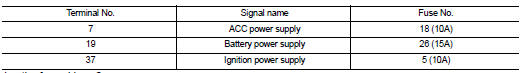
Are the fuses blown? Yes >> replace the blown fuse after repairing the affected circuit.
No >> go to 2.
2.Check power supply circuit
- Turn ignition switch OFF.
- Disconnect AV control unit connectors M103 and M104.
- Check voltage between av control unit connectors m103 and m104 and ground.
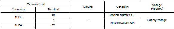
Is the inspection result normal? Yes >> go to 3.
No >> repair or replace harness or connectors.
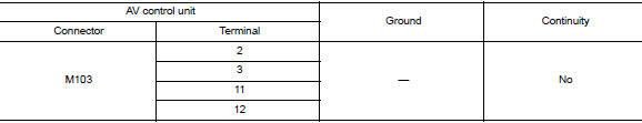
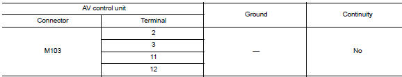
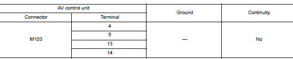
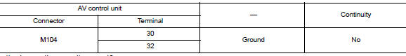
3.Check ground circuit
- Turn ignition switch off.
- Check continuity between av control unit connector m103 and ground.
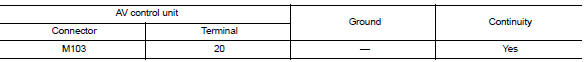
Is the inspection result normal? Yes >> inspection end.
No >> repair or replace harness or connectors.
Front door speaker
Diagnosis Procedure
Regarding wiring diagram information, refer to av-234, "wiring diagram".
1.Connector check
Check the av control unit and speaker connectors for the following:
- Proper connection
- Damage
- Disconnected or loose terminals
Is the inspection result normal? Yes >> go to 2
No >> repair the terminals or connectors.
2.Check front door speaker signal circuit continuity
- Disconnect av control unit connector m103 and suspect front door speaker connector.
- Check continuity between av control unit connector m103 and suspect front door speaker connector.
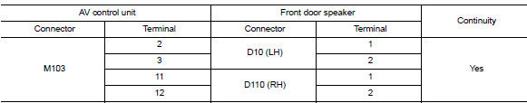
- Check continuity between av control unit connector m103 and ground.
Is the inspection result normal? Yes >> go to 3 no >> repair or replace harness or connectors.
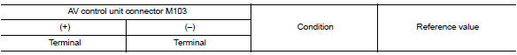
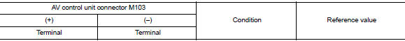
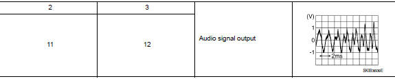
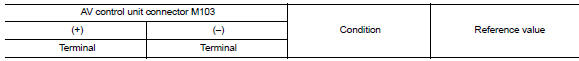
3.Check front door speaker signal
- Connect av control unit connector m103 and suspect front door speaker connector.
- Turn ignition switch to acc.
- Push AV control unit POWER switch.
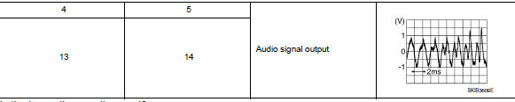
- Check signal between the terminals of av control unit connector m103.
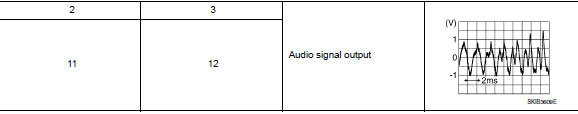
Is the inspection result normal? Yes >> replace front door speaker. Refer to av-300, "removal and installation".
No >> replace av control unit. Refer to av-298, "removal and installation".
Front tweeter
Diagnosis procedure
Regarding wiring diagram information, refer to av-234, "wiring diagram".
1.Connector check
Check the AV control unit and speaker connectors for the following:
- Proper connection
- Damage
- Disconnected or loose terminals
Is the inspection result normal? Yes >> go to 2
No >> repair the terminals or connectors.
2.Check front tweeter signal circuit continuity
- Disconnect AV control unit connector M103 and suspect front tweeter connector.
- Check continuity between AV control unit connector M103 and suspect front tweeter connector.
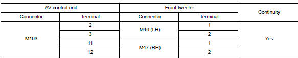
- Check continuity between AV control unit connector M103 and ground.
Is the inspection result normal? Yes >> go to 3
NO >> Repair or replace harness or connectors.
3.Check front tweeter signal
- Connect av control unit connector m103 and suspect front tweeter connector.
- Turn ignition switch to acc.
- Push AV control unit POWER switch.
- Check signal between the terminals of AV control unit connector M103.
Is the inspection result normal? Yes >> replace front tweeter. Refer to av-299, "removal and installation".
No >> replace av control unit. Refer to av-298, "removal and installation".
Rear speaker
Diagnosis procedure
Regarding wiring diagram information, refer to av-234, "wiring diagram".
1.Connector check
Check the av control unit and speaker connectors for the following:
- Proper connection
- Damage
- Disconnected or loose terminals
Is the inspection result normal? Yes >> go to 2
No >> repair the terminals or connectors.
2.Check rear speaker signal circuit continuity
- Disconnect av control unit connector m103 and suspect rear speaker connector.
- Check continuity between AV control unit connector M103 and suspect rear speaker connector.
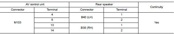
- Check continuity between av control unit connector m103 and ground.
Is the inspection result normal? YES >> GO TO 3
NO >> Repair or replace harness or connectors.
3.Check rear speaker signal
- Connect av control unit connector m103 and suspect rear speaker connector.
- Turn ignition switch to acc.
- Push av control unit power switch.
- Check signal between the terminals of av control unit connector m103.
Is the inspection result normal? Yes >> replace rear speaker. Refer to av-301, "removal and installation".
No >> replace av control unit. Refer to av-298, "removal and installation".
Rear view camera image signal circuit
Diagnosis procedure
Regarding wiring diagram information, refer to av-234, "wiring diagram".
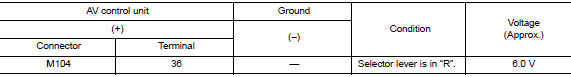
1.Check reverse input signal
- Turn ignition switch ON.
- Shift the selector lever to r (reverse).
- Check voltage between av control unit connector m104 and ground.
Is inspection result normal? Yes >> go to 2.
No >> repair or replace harness or connectors.
2.Check camera power supply circuit continuity
- Turn ignition switch OFF
- Disconnect av control unit connector m104 and rear view camera connector.
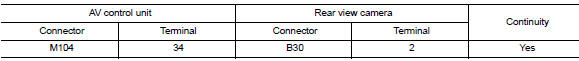
- Check continuity between AV control unit connector M104 and rear view camera connector B30.
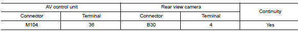
- Check continuity between AV control unit connector M104 and ground.
vIs inspection result normal? Yes >> go to 3.
No >> repair or replace harness or connectors.
3.Check camera power supply voltage
- Connect AV control unit connector M104 and rear view camera connector.
- Turn ignition switch ON.
- Shift the selector lever to r (reverse).
- Check voltage between AV control unit connector M104 and ground.
Is inspection result normal? YES >> GO TO 4.
NO >> Replace AV control unit. Refer to AV-298, "Removal and Installation".
4.Check camera image signal circuit continuity
- Turn ignition switch off.
- Disconnect av control unit connector m104 and rear view camera connector.
- Check continuity between av control unit connector m104 and rear view camera connector b30.
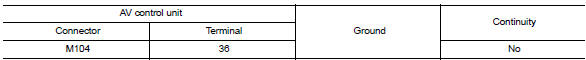
- Check continuity between av control unit connector m104 terminal 34 and ground.

Is inspection result normal? Yes >> go to 5.
No >> repair or replace harness or connectors.
5.Check camera ground circuit continuity
Check continuity between av control unit connector m104 and rear view camera connector b30.
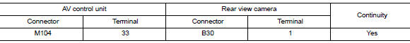
Is inspection result normal? Yes >> go to 6.
No >> repair or replace harness or connectors.
6.Check camera image signal
- Connect av control unit connector m104 and rear view camera connector.
- Turn ignition switch ON.
- Shift the selector lever to r (reverse)
- Check signal between av control unit connector m104 and ground.
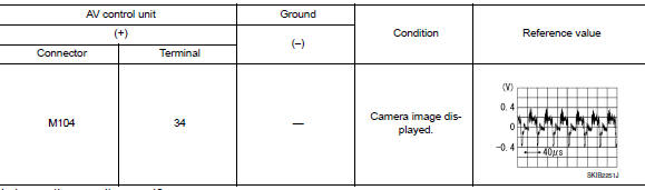
Is inspection result normal? YES >> Replace AV control unit. Refer to AV-298, "Removal and Installation".
NO >> Replace rear view camera. Refer to AV-312, "Removal and Installation".
Microphone signal circuit
Diagnosis procedure
Regarding wiring diagram information, refer to av-234, "wiring diagram".
1.Check microphone signal circuit continuity
- Turn ignition switch off.
- Disconnect AV control unit connector M104 and microphone connector R4.
- Check continuity between av control unit connector m104 and microphone connector r4.
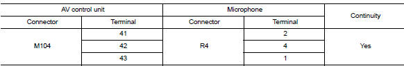
- Check continuity between av control unit connector m104 and ground.
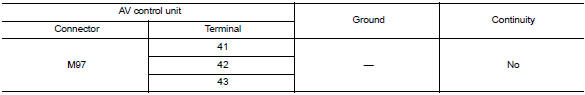
Is inspection result normal? YES >> GO TO 2.
NO >> Repair or replace harness or connectors.
2.Check microphone vcc voltage
- Connect av control unit connector m104.
- Turn ignition switch on.
- Check voltage between terminals of AV control unit connector M104.
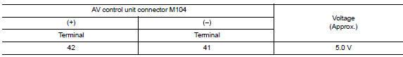
Is the inspection result normal? YES >> GO TO 3.
NO >> Replace AV control unit. Refer to AV-298, "Removal and Installation".
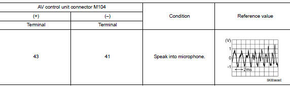
3.Check microphone signal
- Connect microphone connector.
- Check signal between terminals of av control unit connector m104.
Is the inspection result normal? Yes >> replace av control unit. Refer to av-298, "removal and installation".
No >> replace microphone. Refer to av-311, "removal and installation".
Steering switch
Diagnosis procedure
Regarding wiring diagram information, refer to av-234, "wiring diagram".
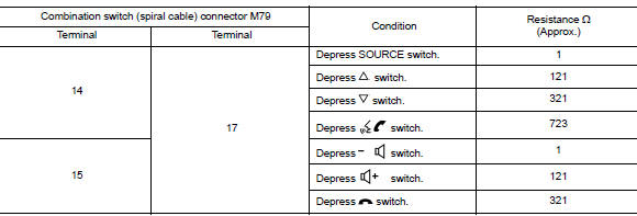
1.Check steering wheel audio control switch resistance
- Turn ignition switch off.
- Disconnect combination switch (spiral cable) connector M79.
- Check resistance between the terminals of combination switch (spiral cable) connector m79.
Is the inspection result normal? Yes >> go to 2.
No >> replace steering switches. Refer to av-302, "removal and installation".
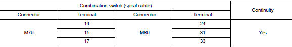
2.Check combination switch (spiral cable)
Check continuity between combination switch (spiral cable) connectors M79 and M80.
Is the inspection result normal? Yes >> go to 3.
No >> replace combination switch (spiral cable). Refer to sr-16, "removal and installation".
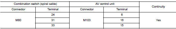
3.Check harness between combination switch (spiral cable) and av control unit
- Disconnect av control unit connector m80.
- Check continuity between combination switch (spiral cable) connector M80 and AV control unit connector M103.
- Check continuity between combination switch (spiral cable) connector m80 and ground.
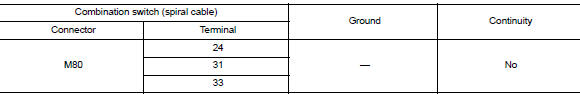
Is the inspection result normal? YES >> Replace AV control unit. Refer to AV-298, "Removal and Installation".
NO >> Repair or replace harness or connectors.
Usb connector
Diagnosis procedure
Regarding wiring diagram information, refer to av-234, "wiring diagram".
1.Check usb interface harness continuity
- Turn ignition switch off.
- Disconnect av control unit connector m113 and usb interface connector m132.
- Check continuity between av control unit connector m113 and usb interface connector m132.
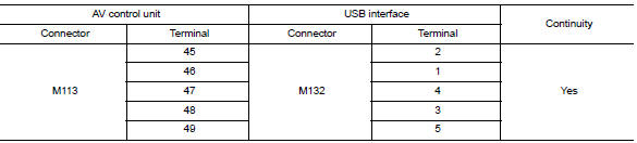
- Check continuity between av control unit connector m113 and ground.
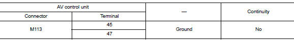
Is the inspection result normal? Yes >> replace the usb interface. Refer to av-307, "removal and installation".
No >> repair or replace harness or connectors.
Auxiliary input jack
Diagnosis procedure
Regarding wiring diagram information, refer to av-234, "wiring diagram".
1.Check aux jack harness continuity
- Turn ignition switch off.
- Disconnect AV control unit connector M104 and AUX jack connector M133.
- Check continuity between av control unit connector m104 and aux jack connector m133.
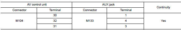
- Check continuity between av control unit connector m104 and ground.
Is the inspection result normal? Yes >> replace the aux jack. Refer to av-307, "removal and installation".
No >> repair or replace harness or connectors.
 Dtc/circuit diagnosis
U1000 can comm circuit
DTC Logic
DTC DETECTION LOGIC
CONSULT Display
DTC Detection Condition
Possible Cause
CAN COMM CIRCUIT
[U1000]
AV control unit is not transmitting ...
 Symptom diagnosis
Multi av system
Symptom table
Related to audio
Related to hands-free phone
Before performing diagnosis, confirm that the cellular phone being used
by the customer is compatible with
...
Other materials:
Precautions for Suspension
When installing rubber bushings, the final tightening must be carried
out under unladen conditions with tires
on ground. Spilled oil might shorten the life of rubber bushings. Be sure to
wipe off any spilled oil.
Unladen conditions mean that fuel, engine coolant and lubricant are
...
Dtc/circuit diagnosis
Power supply and ground circuit
Audio unit
AUDIO UNIT : Diagnosis Procedure
Regarding wiring diagram information, refer to av-88, "wiring diagram".
1.Check fuse
Check that the following fuses are not blown.
Are the fuses blown?
Yes >> replace the blown fuse after repairing ...
Headlamp
Aiming adjustment
Preparation before adjusting
Before performing aiming adjustment, check the following:
Ensure all tires are inflated to correct pressure.
Place vehicle and screen on level surface.
Ensure there is no load in vehicle other than the driver (or equivalent
weight placed in ...
