Nissan Sentra Service Manual: P2765 Input speed sensor B
DTC Logic
DTC DETECTION LOGIC
| DTC | CONSULT screen terms (Trouble diagnosis content) | DTC detection condition | Possible causes |
| P2765 | INPUT SPEED SENSOR B (Input/Turbine Speed Sensor B Circuit) | The secondary speed sensor value is less
than 150 rpm continuously for 5 seconds or
more under the following diagnosis conditions: Diagnosis conditions
|
|
| The secondary pulley speed sensor value is
240 rpm or less continuously for 500 msec or
more under the following diagnosis conditions: Diagnosis condition
|
DTC CONFIRMATION PROCEDURE
CAUTION:
Be careful of the driving speed.
1.PREPARATION BEFORE WORK
If another “DTC CONFIRMATION PROCEDURE” occurs just before, turn ignition switch OFF and wait for at least 10 seconds, then perform the next test.
>> GO TO 2.
2.CHECK DTC DETECTION
- Start the engine
- Drive the vehicle
- Maintain the following conditions for 10 seconds or more.
Selector lever : “D” position
Vehicle speed : 55 km/h (34 MPH) or more
- Stop the vehicle.
- Check the first trip DTC.
Is “P2765” detected? YES >> Go to TM-223, "Diagnosis Procedure".
NO >> INSPECTION END
Diagnosis Procedure
1.CHECK SECONDARY SPEED SENSOR POWER CIRCUIT
- Turn ignition switch OFF.
- Disconnect secondary speed sensor connector.
- Turn ignition switch ON.
- Check voltage between secondary speed sensor harness connector terminal and ground.
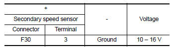
Is the inspection result normal? YES >> GO TO 2.
NO >> GO TO 6.
2.CHECK SECONDARY SPEED SENSOR GROUND CIRCUIT
Check continuity between of secondary speed sensor harness connector terminal and ground.
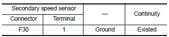
Is the inspection result normal? YES >> GO TO 3.
NO >> Repair or replace malfunctioning parts.
3.CHECK CIRCUIT BETWEEN SECONDARY SPEED SENSOR AND TCM (PART 1)
- Turn ignition switch OFF.
- Disconnect TCM connector.
- Check continuity between secondary speed sensor harness connector terminal and TCM harness connector terminal.
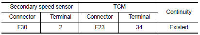
Is the inspection result normal? YES >> GO TO 4.
NO >> Repair or replace malfunctioning parts.
4.CHECK CIRCUIT BETWEEN SECONDARY SPEED SENSOR AND TCM (PART 2)
Check continuity between secondary speed sensor harness connector terminal and ground.
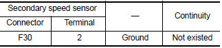
Is the inspection result normal? YES >> GO TO 5.
NO >> Repair or replace malfunctioning parts.
5.Check TCM Input signals
- Connect all of disconnected connectors.
- Lift the vehicle.
- Start the engine.
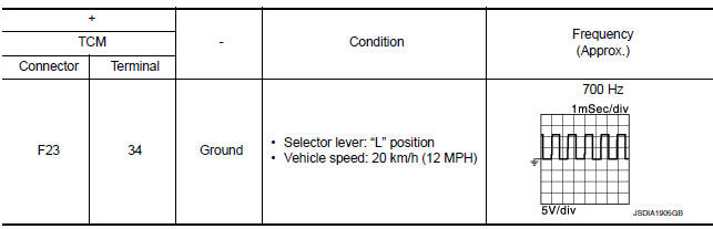
- Check frequency of secondary speed sensor.
Is the inspection result normal? YES >> Check intermittent incident. Refer to GI-39, "Intermittent Incident".
NO >> Replace secondary speed sensor. TM-269, "Removal and Installation".
6.DETECT MALFUNCTIONING ITEMS
Check the following items:
- Harness open circuit or short circuit between ignition switch and IPDM E/R. Refer to PG-20, "Wiring Diagram — Ignition Power Supply —".
- Harness open circuit or short circuit between IPDM E/R and secondary speed sensor.
- 10A fuse (No.45, IPDM E/R). Refer to PG-49, "IPDM E/R Terminal Arrangement".
- IPDM E/R
Is the check result normal? YES >> Check intermittent incident. Refer to GI-39, "Intermittent Incident".
NO >> Repair or replace malfunctioning parts.
 P1588 G Sensor
DTC Logic
DTC DETECTION LOGIC
DTC
CONSULT screen terms
(Trouble diagnosis content)
DTC detection condition
Possible causes
P1588
G Sensor
(Gravity S ...
 P2857 Clutch A Pressure
DTC Logic
DTC DETECTION LOGIC
DTC
CONSULT screen terms
(Trouble diagnosis content)
DTC detection condition
Possible causes
P2857
CLUTCH A PRESSURE
(Clutch A Pressu ...
Other materials:
Rear shock absorber
Exploded View
Rear suspension beam
Shock absorber
Bound bumper
Bound bumper cover
Washer
Bushing
Distance tube
Bushing
Washer
Piston rod lock nut
Cap
Front
Removal and Installation
REMOVAL
Remove the rear shock tower access flap.
Remove the cap from the rear s ...
Main line between dlc and hvac circuit
Diagnosis Procedure
1.Check harness continuity (open circuit)
Turn the ignition switch OFF.
Disconnect the battery cable from the negative terminal.
Disconnect the following harness connectors.
Ecm
A/c auto amp.
Check the continuity between the data link connector and the a/c ...
Handling precautions for plastics
Precautions for plastics
When repairing and painting a portion of the body adjacent to plastic
parts, consider their characteristics
(influence of heat and solvent) and remove them if necessary or take
suitable measures to protect them.
Plastic parts should be repaired and painted ...
