Nissan Sentra Service Manual: P0130 A/F Sensor 1
DTC Logic
DTC DETECTION LOGIC
To judge the malfunction, the diagnosis checks that the A/F signal computed by ECM from the A/F sensor 1 signal fluctuates according to fuel feedback control.
| DTC No. | CONSULT screen terms (Trouble diagnosis content) | DTC detecting condition | Possible cause | |
| P0130 | A/F SENSOR1 (B1) (O2 sensor circuit bank 1 sensor 1) | A) | The A/F signal computed by ECM from the A/F sensor 1 signal is constantly in the range other than approx. 2.2 V. |
|
| B) | The A/F signal computed by ECM from the A/F sensor 1 signal is constantly approx. 2.2 V. | |||
DTC CONFIRMATION PROCEDURE
1.PRECONDITIONING
- If DTC Confirmation Procedure has been previously conducted, always perform the following procedure before conducting the next test.
- Turn ignition switch OFF and wait at least 10 seconds.
- Turn ignition switch ON.
- Turn ignition switch OFF and wait at least 10 seconds.
TESTING CONDITION:
Before performing the following procedure, confirm that battery voltage is more than 11 V at idle.
>> GO TO 2.
2.PERFORM DTC CONFIRMATION PROCEDURE FOR MALFUNCTION A
 With CONSULT
- Start engine and warm it up to normal operating temperature.
- Let it idle for 2 minutes.
- Check 1st trip DTC.
Is 1st trip DTC detected? YES >> Proceed to EC-211, "Diagnosis Procedure".
NO-1 (  With CONSULT)>>GO TO 3.
NO-2 (  Without CONSULT)>>GO TO 7.
3.CHECK AIR FUEL RATIO (A/F) SENSOR 1 FUNCTION
- Select ą▓ąéčÜA/F SEN1 (B1)ą▓ąéč£ in ą▓ąéčÜDATA MONITORą▓ąéč£ mode of ą▓ąéčÜENGINEą▓ąéč£ using CONSULT.
- Check ą▓ąéčÜA/F SEN1 (B1)ą▓ąéč£ indication.
Does the indication fluctuates around 2.2 V? YES >> GO TO 4.
NO >> Proceed to EC-211, "Diagnosis Procedure".
4.PERFORM DTC CONFIRMATION PROCEDURE FOR MALFUNCTION B-1
- Select ą▓ąéčÜA/F SEN1 (B1) P1276ą▓ąéč£ of ą▓ąéčÜA/F SEN1ą▓ąéč£ in ą▓ąéčÜDTC WORK SUPPORTą▓ąéč£ mode of ą▓ąéčÜENGINEą▓ąéč£ using CONSULT.
- Touch ą▓ąéčÜSTARTą▓ąéč£.
- When the following conditions are met, ą▓ąéčÜTESTINGą▓ąéč£ will be displayed on the CONSULT screen.
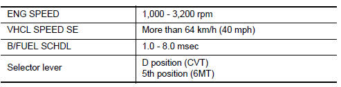
If ą▓ąéčÜTESTINGą▓ąéč£ is not displayed after 20 seconds, retry from step 2.
CAUTION:
Always drive vehicle at a safe speed.
Is ą▓ąéčÜTESTINGą▓ąéč£ displayed on CONSULT screen? YES >> GO TO 5.
NO >> 1. Check A/F sensor 1 function again.
2. GO TO 3.
5.PERFORM DTC CONFIRMATION PROCEDURE FOR MALFUNCTION B-2
Release accelerator pedal fully.
NOTE:
Never apply brake during releasing the accelerator pedal.
Which does ą▓ąéčÜTESTINGą▓ąéč£ change to? COMPLETED>>GO TO 6.
OUT OF CONDITION>>1.Retry DTC CONFIRMATION PROCEDURE.
2. GO TO 4.
6.PERFORM DTC CONFIRMATION PROCEDURE FOR MALFUNCTION B-3
Touch ą▓ąéčÜSELF-DIAG RESULTą▓ąéč£ Which is displayed on CONSULT screen? YES >> INSPECTION END
NO >> Proceed to EC-211, "Diagnosis Procedure".
7.PERFORM COMPONENT FUNCTION CHECK FOR MALFUNCTION B
Perform Component Function Check. Refer to EC-211, "Component Function Check".
NOTE:
Use component function check to check the overall function of the A/F sensor 1 circuit. During this check, a 1st trip DTC might not be confirmed.
Is the inspection result normal? YES >> INSPECTION END
NO >> Proceed to EC-211, "Diagnosis Procedure".
Component Function Check
1.PERFORM COMPONENT FUNCTION CHECK
 With GST
- Start engine and warm it up to normal operating temperature.
- Drive the vehicle at a speed of 80 km/h (50 MPH) for a few minutes in the suitable gear position.
- Shift the selector lever to the D position (CVT) or 5th position (M/T), then release the accelerator pedal fully until the vehicle speed decreases to 50 km/h (31 MPH).
CAUTION:
Always drive vehicle at a safe speed.
NOTE:
Never apply brake during releasing the accelerator pedal.
- Repeat steps 2 to 3 for five times.
- Stop the vehicle and turn ignition switch OFF.
- Wait at least 10 seconds and restart engine.
- Repeat steps 2 to 3 for five times
- Stop the vehicle.
- Check 1st trip DTC.
Is 1st trip DTC detected? YES >> Proceed to EC-211, "Diagnosis Procedure".
NO >> INSPECTION END
Diagnosis Procedure
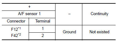
1.CHECK AIR FUEL RATIO (A/F) SENSOR 1 POWER SUPPLY
- Turn ignition switch OFF.
- Disconnect A/F sensor 1 harness connector.
- Turn ignition switch ON.
- Check the voltage between A/F sensor 1 harness connector and ground.
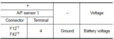
*1: Except California
*2: For California
Is the inspection result normal? YES >> GO TO 3.
NO >> GO TO 2.
2.CHECK AIR FUEL RATIO (A/F) SENSOR 1 POWER SUPPLY CIRCUIT
- Turn ignition switch OFF.
- Disconnect IPDM E/R harness connector
- Check the continuity between A/F sensor 1 harness connector and IPDM E/R harness connector.
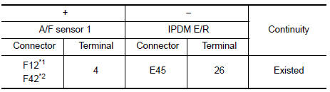
*1: Except California
*2: For California
- Also check harness for short to ground.
Is the inspection result normal? YES >> Perform the trouble diagnosis for power supply circuit.
NO >> Repair or replace error-detected parts.
3.CHECK A/F SENSOR 1 INPUT SIGNAL CIRCUIT
- Turn ignition switch OFF.
- Disconnect ECM harness connector.
- Check the continuity between A/F sensor 1 harness connector and ECM harness connector.
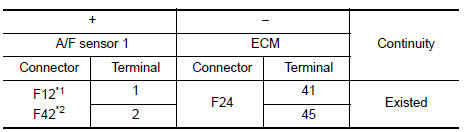
*1: Except California
*2: For California
- Check the continuity between A/F sensor 1 harness connector and ground, or ECM harness connector and ground.
*1: Except California
*2: For California
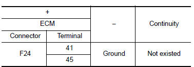
- Also check harness for short to power.
Is the inspection result normal? YES >> GO TO 4.
NO >> Repair or replace error-detected parts.
4.CHECK INTERMITTENT INCIDENT
Check intermittent incident. Refer to GI-39, "Intermittent Incident".
Is the inspection result normal? YES >> Replace air fuel ratio (A/F) sensor 1. Refer to EM-30, "Exploded View".
NO >> Repair or replace error-detected parts.
 P0128 Thermostat function
DTC Logic
DTC DETECTION LOGIC
NOTE:
If DTC P0128 is displayed with DTC P0300, P0301, P0302, P0303 or P0304,
first perform the trouble
diagnosis for P0300, P0301, P0302, P0303 or P0304. Refer to ...
 P0131 A/F Sensor 1
DTC Logic
DTC DETECTION LOGIC
To judge the malfunction, the diagnosis checks that the A/F signal computed
by ECM from the A/F sensor 1
signal is not inordinately low.
DTC No.
CONSULT s ...
Other materials:
System
System Diagram
FRONT POWER WINDOW LH ANTI-PINCH SYSTEM
System Description
MAIN POWER WINDOW AND DOOR LOCK/UNLOCK SWITCH
INPUT/OUTPUT SIGNAL CHART
Item
Input signal to main power window and
door lock/unlock switch
Main power window and door
lock/unlock switch function
A ...
Booster seats
Precautions on booster seats
WARNINGIf a booster seat and seat belt are not
used
properly, the risk of a child being injured in
a sudden stop or collision greatly
increases:
Make sure the shoulder portion of
the belt is away from the childŌĆÖs face
and neck and t ...
Diagnosis system (BCM)
Common item
Common item : consult function (bcm - common item)
Application item
Consult performs the following functions via can communication with bcm.
Direct diagnostic mode
Description
Ecu identification
The bcm part number is displayed.
Self Diagnostic Result
...
