Nissan Sentra Service Manual: Fuel pressure
Work Procedure
FUEL PRESSURE RELEASE
1.FUEL PRESSURE RELEASE
 With CONSULT
- Turn ignition switch ON.
- Perform đ▓đéĐÜFUEL PRESSURE RELEASEđ▓đéĐť in đ▓đéĐÜWORK SUPPORTđ▓đéĐť mode of đ▓đéĐÜENGINEđ▓đéĐť using CONSULT
- Start engine.
- After engine stalls, crank it two or three times to release all fuel pressure.
- Turn ignition switch OFF.
 Without CONSULT
- Remove fuel pump fuse located in IPDM E/R.
- Start engine.
- After engine stalls, crank it two or three times to release all fuel pressure.
- Turn ignition switch OFF.
- Reinstall fuel pump fuse after servicing fuel system.
>> END
FUEL PRESSURE CHECK
CAUTION:
- Before disconnecting fuel line, release fuel pressure from fuel line to eliminate danger
- The fuel hose connection method used when taking fuel pressure check must not be used for other purposes.
- Be careful not to scratch or put debris around connection area when servicing, so that the quick connector maintains sealability with O-rings inside.
- Do not perform fuel pressure check with electrical systems operating (i.e. lights, rear defogger, A/C, etc.) Fuel pressure gauge may indicate false readings due to varying engine load and changes in manifold vacuum.
NOTE:
Prepare pans or saucers under the disconnected fuel line because the fuel may spill out. The fuel pressure cannot be completely released because this models do not have fuel return system.
1.FUEL PRESSURE CHECK
- Release fuel pressure to zero.
- Prepare fuel hose for fuel pressure check (B) and fuel tube adapter [SST: KV1011840] (D), then connect fuel pressure gauge (A).
 To quick connector
 To fuel tube
 Clamp
Clamp
CAUTION:
- Use suitable fuel hose for fuel pressure check (genuine NISSAN fuel hose without quick connector).
- To avoid unnecessary force or tension to hose, use moderately long fuel hose for fuel pressure check.
- Do not use the fuel hose for checking fuel pressure with damage or cracks on it.
- Use Pressure Gauge to check fuel pressure.
- Remove fuel hose.
CAUTION:
Do not twist or kink fuel hose because it is plastic hose.
- Connect fuel hose for fuel pressure check
 to fuel tube
 with
with
clamp as shown in the figure.
5: No. 2 spool
CAUTION:
- Wipe off oil or dirt from hose insertion part using cloth moistened with gasoline.
- Apply proper amount of gasoline between top of the fuel tube and No. 1 spool .
- Insert fuel hose for fuel pressure check until it touches the No. 1 spool on fuel tube.
- Use NISSAN genuine hose clamp (part number: 16439 N4710 or 16439 40U00).
- When reconnecting fuel line, always use new clamps.
- Use a torque driver to tighten clamps.
Tightening torque: 1 - 1.5 Nđĺ┬Ěm (0.1 - 0.15 kg-m, 9 - 13 in-lb)
- Install hose clamp to the position within 1 - 2 mm (0.04 - 0.08 in).
- Make sure that clamp screw does not contact adjacent parts.
- Connect fuel tube adapter to quick connector.
A :Fuel pressure gauge
B :Fuel hose for fuel pressure check
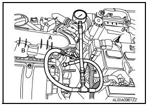
After connecting fuel hose for fuel pressure check, pull the hose with a force of approximately 98 N (10 kg, 22 lb) to confirm high pressure fuel pump does not come off.
- Turn ignition switch ON and check for fuel leakage.
- Start engine and check for fuel leakage.
- Read the indication of fuel pressure gauge.
CAUTION:
- Do not perform fuel pressure check with system operating.
Fuel pressure gauge may indicate false readings.
- During fuel pressure check, confirm for fuel leakage from fuel connection every 3 minutes.
At idling : Approximately 350 kPa (3.5 bar, 3.57 kg/cm2, 51 psi)
Is the inspection result normal? YES >> INSPECTION END
NO >> GO TO 2.
2.CHECK FUEL HOSES
Check the following.
- Fuel hoses for clogging
- Fuel filter for clogging
- Fuel pump
- Fuel pressure regulator for clogging
Is the inspection result normal?
YES >> Replace fuel pressure regulator.
NO >> Repair or replace error-detected parts.
 Mixture ratio self-learning value
clear
Mixture ratio self-learning value
clear
Description
This describes how to erase the mixture ratio self-learning value. For the
actual procedure, follow the instructions
in đ▓đéĐÜDiagnosis Proceduređ▓đéĐť.
Work Procedure
1.START
With ...
 How to set srt code
Description
OUTLINE
In order to set all SRTs, the self-diagnoses as in the đ▓đéĐÜSRT ITEMđ▓đéĐť table must
have been performed at least
once. Each diagnosis may require actual driving for a long ...
Other materials:
Condenser
Exploded view
Core support upper cover
High-pressure pipe
High-pressure flexible hose
Refrigerant pressure sensor
Condenser and liquid tank assembly
Core support upper
Front
Condenser
Condenser : removal and installation
REMOVAL
Discharge the refrigerant. Refer to HA-23, & ...
Diagnosis system (BCM) (without intelligent key system)
Common item
Common item : consult function (bcm - common item)
APPLICATION ITEM
CONSULT performs the following functions via CAN communication with BCM.
Direct Diagnostic Mode
Description
ECU identification
The BCM part number is displayed.
Self Diagnostic Result
...
List of voice commands
Main Menu
ÔÇťCallÔÇŁ
ÔÇťPhonebookÔÇŁ
ÔÇťRecent CallsÔÇŁ
ÔÇťConnect PhoneÔÇŁ
When you press and release the
button on
the steering wheel, you can choose from the
commands on the Main Menu. The following
pages describe these commands and the commands
in each sub-menu.
Remember to wai ...
