Nissan Sentra Service Manual: Fuel injector and fuel tube
Exploded View
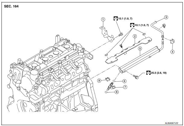
- Bracket
- Fuel tube bracket
- Fuel feed tube
- Quick connector cap
- Fuel tube
- O-ring (black)
- Fuel injector
- O-ring (green)
- Injector clip
CAUTION:
Do not remove or disassemble parts unless instructed.
Removal and Installation
WARNING:
- Put a “CAUTION: FLAMMABLE” sign in the workshop.
- Be sure to work in a well ventilated area and furnish workshop with a CO2 fire extinguisher.
- Do not smoke while servicing fuel system. Keep open flames and sparks away from the work area.
REMOVAL
- Remove engine room cover. Refer to EM-24, "Exploded View".
- Release the fuel pressure. Refer to EC-143, "Work Procedure".
- Remove intake manifold. Refer to EM-27, "Exploded View".
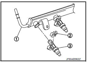
- Disconnect quick connector with the following procedure. Disconnect fuel feed tube (1) from fuel tube (3).
NOTE:
There is no fuel return path.
- Remove quick connector cap (engine side) (2) from quick connector connection.
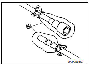
- With the sleeve (B) side of Tool (A) facing quick connector, install Tool (A) onto fuel tube.
- Insert Tool (A) into quick connector (2) until sleeve (B) contacts and goes no further. Hold quick connector release on that position (C).
(D) : Insert and retain
CAUTION:
Inserting quick connector release hard will not disconnect quick connector. Hold quick connector release where it contacts and goes no further.
Draw and pull out quick connector straight from fuel tube (1).
CAUTION:
- Pull quick connector (E) holding position (C).
- Do not pull with lateral force applied. O-ring inside quick connector may be damaged.
- Prepare container and cloth beforehand as fuel will leak out.
- Avoid fire and sparks.
- Keep parts away from heat source. Especially, be careful when welding is performed around them.
- Do not expose parts to battery electrolyte or other acids.
- Do not bend or twist connection between quick connector and fuel feed tube during installation/ removal.
- To keep the connecting portion clean and to avoid damage and foreign materials, cover them completely with plastic bags, etc. (A) or something similar.
- Disconnect harness connector from fuel injector.
- Loosen fuel tube bracket nuts and end bolts and remove fuel tube brackets.
- Remove fuel tube and fuel injector assembly.
- Loosen bolts in the reverse order as shown.
CAUTION:
- When removing, be careful to avoid any interference with fuel injector.
- Use a shop cloth to absorb any fuel leaks from fuel tube.
- Remove fuel injector from fuel tube with the following procedure:
- Open and remove clip (2)
- Remove fuel injector (3) from fuel tube (1) by pulling straight.
CAUTION:
- Be careful with remaining fuel that may leak from fuel tube.
- Be careful not to damage fuel injector nozzle during removal.
- Do not bump or drop fuel injector.
- Do not disassemble fuel injector.
INSTALLATION
- Install O-rings to fuel injector.
CAUTION:
- Do not reuse O-ring.
- Upper and lower O-rings are different. Be careful not to confuse them.
Fuel tube side : Black
Nozzle side : Green
- Handle O-ring with bare hands. Do not wear gloves.
- Lubricate O-ring with new engine oil.
- Do not clean O-ring with solvent.
- Check that O-ring and its mating part are free of foreign material.
- When installing O-ring, be careful not to scratch it with tool or fingernails. Also be careful not to twist or stretch O-ring. If O-ring is stretched while installing, do not insert it quickly into fuel tube.
- Insert O-ring straight onto fuel injector. Do not decenter or twist it.
- Install fuel injector to fuel tube with the following procedure:
- Insert clip (2) into clip mounting groove (F) on fuel injector (4).
(3) : O-ring (black)
(5) : O-ring (green)
- Insert clip so that protrusion (G) of fuel injector matches cutout (D) of clip.
CAUTION:
- Do not reuse clip. Replace it with a new one.
- Be careful to keep clip from interfering with O-ring. If interference occurs, replace O-ring.
- Insert fuel injector into fuel tube (1) with clip attached.
- Insert it while matching it to the axial center.
- Insert fuel injector so that protrusion (B) of fuel tube matches cut-out (C) of clip.
- Check that fuel tube flange (A) is securely locked in flange groove (E) on clip.
- Check that installation is complete by checking that fuel injector does not rotate or come off.
- Set fuel tube and fuel injector assembly at its position for installation on cylinder head.
CAUTION:
For installation, be careful not to interfere with fuel injector nozzle.
- Install fuel tube and injector assembly onto cylinder head.
- Tighten bolts in the order as shown.
- Connect harness connector to fuel injector.
- Install fuel tube bracket.
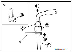
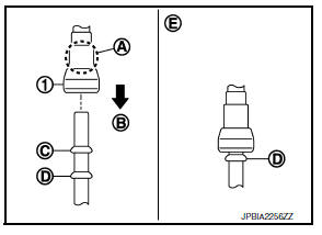
- Connect fuel feed tube with the following procedure.
- Check for damage or foreign material on the fuel tube and quick connector.
- Apply new engine oil lightly to area around the top of fuel tube.
- Align center to insert quick connector straightly into fuel tube.
- Insert quick connector (1) to fuel tube until the top spool (3) on fuel tube is inserted completely and the 2nd level spool (D) is positioned slightly below quick connector bottom end.
(B) : Insertion direction
(E) : Fitted condition
CAUTION:
- Hold (A) position when inserting fuel tube into quick connector.
- Carefully align center to avoid inclined insertion to prevent damage to O-ring inside quick connector.
- Insert until you hear a “click” sound and actually feel the engagement.
- To avoid misidentification of engagement with a similar sound, be sure to perform the next step.
- Pull quick connector hard by hand holding position. Check it is completely engaged (connected) so that it does not come out from fuel tube.
- Install quick connector cap (engine side) (2) to quick connector connection.
(1) : Fuel feed hose
(3) : Fuel tube
- Install quick connector cap (engine side) with the side arrow facing quick connector side (fuel feed tube side).
CAUTION:
- Check that the quick connector and fuel tube are securely engaged with the quick connector cap (engine side) mounting groove.
- Quick connector may not be connected correctly if quick connector cap (engine side) cannot be installed easily. Remove the quick connector cap (engine side), and then check the connection of quick connector again.
- Install fuel feed hose to hose clamp.
- Installation of remaining components is in the reverse order of removal.
Inspection
INSPECTION AFTER INSTALLATION
Check on Fuel Leakage
- Turn ignition switch “ON” (with the engine stopped). With fuel pressure applied to fuel piping, check there are no fuel leaks at connection points. Refer to.
NOTE:
Use mirrors for checking at points out of clear sight.
- Start the engine. With engine speed increased, check again that there are no fuel leaks at connection points.
- Perform procedures for “Throttle Valve Closed Position Learning” after finishing repairs. Refer to EC- 139, "Description".
- If electric throttle control actuator is replaced, perform procedures for “Idle Air Volume Learning” after finishing repairs. Refer to EC-140, "Description".
CAUTION:
Do not touch the engine immediately after stopping, as the engine becomes extremely hot.
 Oil pan
Exploded View
O-ring
Oil pan (upper)
Oil level gauge guide
O-ring
Oil level gauge
Oil pump drive chain
Crankshaft sprocket
Oil pump sprocket
Oil pump chain tensioner
Oil pump
...
 Ignition coil
Exploded View
Ignition coil
Spark plug
Rocker cover
Removal and Installation
REMOVAL
Remove the engine room cover. Refer to EM-24, "Exploded View".
Disconnect the harne ...
Other materials:
Moonroof switch
Description
Transmits switch operation signal to moonroof motor assembly.
Diagnosis Procedure
Regarding Wiring Diagram information, refer to RF-13, "Wiring Diagram".
1.Check moonroof switch input signal
Turn ignition switch on.
Check voltage between moonroof motor assembly harne ...
Engine compartment check locations
MRA8DE engine
Engine oil filler cap
Brake and clutch (if so equipped) fluid
reservoir
Air cleaner
Battery
Fuse/fusible link box
Engine coolant reservoir
Radiator cap
Engine oil dipstick
Drive belt location
Windshield-washer fluid reservoir
...
P0197, P0198 EOTSensor
DTC Logic
DTC DETECTION LOGIC
DTC No.
CONSULT screen terms
(Trouble diagnosis content)
DTC detecting condition
Possible cause
P0197
EOT SEN/CIRC
(Engine oil temperature
sensor circuit low)
An excessively low voltage from the engine
oil temperature sensor ...
