Nissan Sentra Service Manual: DTC/circuit diagnosis
POWER SUPPLY AND GROUND CIRCUIT
A/C AUTO AMP.
A/C AUTO AMP. : Diagnosis Procedure
Regarding Wiring Diagram information, refer to HAC-145, "Wiring Diagram" or HAC-152, "Wiring Diagram".
1.CHECK FUSE
Check fuses [No. 5, 8 and 21, located in the fuse block (J/B)].
NOTE:
Refer to PG-47, "Terminal Arrangement".
Is the inspection result normal? YES >> GO TO 2.
NO >> Replace the blown fuse after repairing the affected circuit.
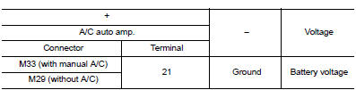
2.Check A/C Auto AMP. Power supply
- Turn ignition switch OFF.
- Disconnect A/C auto amp. connector.
- Check voltage between A/C auto amp. harness connector and ground.
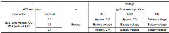
Is the inspection result normal? YES >> GO TO 3.
NO >> Repair harness or connector between A/C auto amp. and fuse block (J/B).
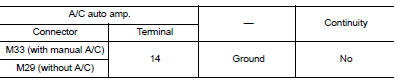
3.Check A/C Auto AMP. Ground circuit
- Turn ignition switch OFF.
- Check continuity between A/C auto amp. harness connector and ground.
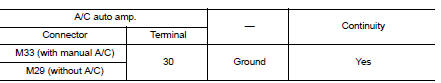
Is the inspection result normal? YES >> Inspection End.
NO >> Repair harness or connector.
A/C SWITCH ASSEMBLY
A/C SWITCH ASSEMBLY : Component Function Check
1.CHECK OPERATION
- Press the ON switch.
- Operate the temperature control switch. Check that the fan speed or outlet changes.
Does it operate normally?
YES >> Inspection End.
NO >> Perform trouble diagnosis for the A/C switch assembly. Refer to HAC-160, "A/C SWITCH ASSEMBLY : Diagnosis Procedure".
A/C SWITCH ASSEMBLY : Diagnosis Procedure
Regarding Wiring Diagram information, refer to HAC-145, "Wiring Diagram" or HAC-152, "Wiring Diagram".
1.Check A/C Switch assembly power supply
- Disconnect the A/C switch assembly connector.
- Turn ignition switch ON.
- Check voltage between A/C switch assembly harness connector and ground.
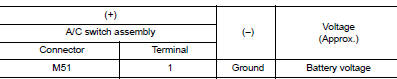
Is the inspection result normal? YES >> GO TO 3.
NO >> GO TO 2.
2.CHECK FUSE
Check 10A fuse [No.5, located in the fuse block (J/B)].
NOTE:
Refer to PG-47, "Terminal Arrangement".
Is the inspection result normal? YES >> Check harness for open circuit. Repair or replace if necessary.
NO >> Check harness for short circuit. Repair or replace if necessary.
3.Check a/c switch assembly ground circuit
- Turn ignition switch OFF.
- Check continuity between A/C switch assembly harness connector and ground.
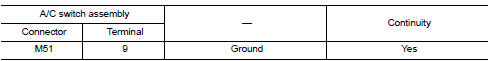
Is the inspection result normal? YES >> Replace the A/C switch assembly. Refer to HAC-188, "Removal and Installation".
NO >> Repair the harnesses or connectors.
MODE DOOR MOTOR
Diagnosis Procedure
Regarding Wiring Diagram information, refer to HAC-145, "Wiring Diagram" or HAC-152, "Wiring Diagram".
1.Check mode door motor power supply
- Turn ignition switch OFF.
- Disconnect mode door motor connector.
- Turn ignition switch on.
- Check voltage between mode door motor harness connector and ground.
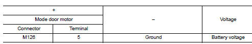
Is the inspection result normal? Yes >> go to 2.
No >> repair harness or connector between mode door motor and fuse.
2.Check mode door motor drive signal circuit for open
- Turn ignition switch OFF.
- Disconnect a/c auto amp. Connector.
- Check continuity between mode door motor harness connector and a/c auto amp. Harness connector.
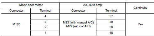
Is the inspection result normal? YES >> GO TO 3.
NO >> Repair harness or connector.
3.Check mode door motor drive signal circuit for short
Check continuity between mode door motor harness connector and A/C auto amp. harness connector.
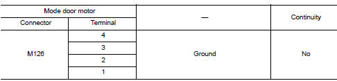
Is the inspection result normal? Yes >> go to 4.
No >> repair harness or connector.
4.Check mode door motor
Check mode door motor. Refer to hac-162, "component inspection".
Is the inspection result normal? YES >> Replace A/C auto amp. Refer to HAC-189, "Removal and Installation".
NO >> Replace mode door motor. Refer to HAC-193, "MODE DOOR MOTOR : Removal and Installation".
Component Inspection
1.Check mode door motor
- Remove mode door motor. Refer to hac-193, "mode door motor : removal and installation".
- Check resistance between mode door motor terminals. Refer to applicable table for the normal value.
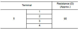
Is the inspection result normal? Yes >> inspection end.
No >> replace mode door motor. Refer to hac-193, "mode door motor : removal and installation".
AIR MIX DOOR MOTOR
Diagnosis Procedure
Regarding wiring diagram information, refer to hac-145, "wiring diagram" or hac-152, "wiring diagram".
1.Check air mix door motor power supply
- Turn ignition switch off.
- Disconnect air mix door motor connector.
- Turn ignition switch on.
- Check voltage between air mix door motor harness connector and ground.
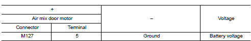
Is the inspection result normal? Yes >> go to 2.
No >> repair harness or connector between air mix door motor and fuse.
2.Check air mix door motor drive signal circuit for open
- Turn ignition switch OFF.
- Disconnect a/c auto amp. Connector.
- Check continuity between air mix door motor harness connector and a/c auto amp. Harness connector.
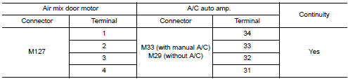
Is the inspection result normal? Yes >> go to 3.
No >> repair harness or connector.
3.Check air mix door motor drive signal circuit for short
Check continuity between air mix door motor harness connector and a/c auto amp. Harness connector.
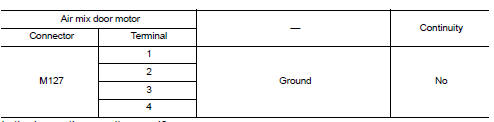
Is the inspection result normal? Yes >> go to 4.
No >> repair harness or connector.
4.Check air mix door motor
Check air mix door motor. Refer to hac-164, "component inspection".
Is the inspection result normal? YES >> Replace A/C auto amp. Refer to HAC-189, "Removal and Installation".
NO >> Replace air mix door motor. Refer to HAC-193, "AIR MIX DOOR MOTOR : Removal and Installation".
Component Inspection
1.Check air mix door motor
- Remove air mix door motor. Refer to hac-193, "air mix door motor : removal and installation".
- Check resistance between air mix door motor terminals. Refer to applicable table for the normal value.
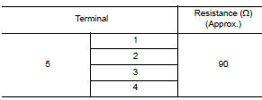
Is the inspection result normal? Yes >> inspection end.
No >> replace air mix door motor. Refer to hac-193, "air mix door motor : removal and installation".
INTAKE DOOR MOTOR
Diagnosis Procedure
Regarding wiring diagram information, refer to hac-145, "wiring diagram" or hac-152, "wiring diagram".
1.Check intake door motor operation
- Turn ignition switch on.
- Operate intake switch and check by operation sound that intake door motor operates.
Does the intake door motor operate? Yes >> refer to gi-39, "intermittent incident".
No >> go to 2.
2.Check intake door motor drive signal circuit for open
- Turn ignition switch OFF.
- Disconnect intake door motor connector, and a/c auto amp. Connector.
- Check continuity between intake door motor harness connector and a/c auto amp. Harness connector.
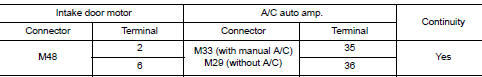
Is the inspection result normal? Yes >> go to 3.
No >> repair harness or connector.
3.Check intake door motor drive signal circuit for short
Check continuity between intake door motor harness connector and ground.
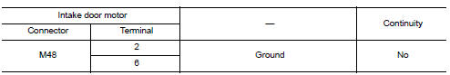
Is the inspection result normal? Yes >> go to 4.
No >> repair harness or connector.
4.Check intake door motor
- Turn ignition switch off.
- Check intake door motor. Refer to hac-166, "component inspection (motor)".
Is the inspection result normal? YES >> GO TO 5.
NO >> Replace intake door motor. Refer to HAC-193, "INTAKE DOOR MOTOR : Removal and Installation".
5.Check installation of intake door motor system
Check intake door motor system is properly installed. Refer to hac-192, "exploded view".
Is the inspection result normal? Yes >> replace a/c auto amp. Refer to hac-189, "removal and installation".
No >> repair or replace malfunctioning parts.
Component Inspection (Motor)
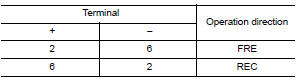
1.Check intake door motor
Supply intake door motor terminals with battery voltage and check by visually and operation sound that intake door motor operates.
Is the inspection result normal? Yes >> inspection end.
No >> replace intake door motor. Refer to hac-193, "intake door motor : removal and installation".
A/C SWITCH ASSEMBLY SIGNAL CIRCUIT
Diagnosis Procedure
Regarding wiring diagram information, refer to hac-145, "wiring diagram" or hac-152, "wiring diagram".
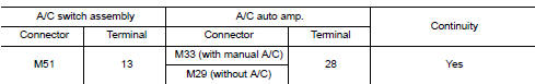
1.Check rx (a/c switch assembly ƒ¸ a/c auto amp.) Circuit continuity
- Turn ignition switch off
- Disconnect the a/c switch assembly and the a/c auto amp. Connectors
- Check continuity between A/C switch assembly harness connector and A/C auto amp. harness connector
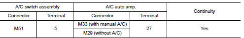
- Check continuity between A/C switch assembly harness connector M51 terminal 5 and ground.
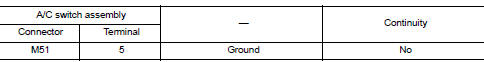
Is the inspection result normal? Yes >> go to 2.
No >> repair harness or connector.
2.Check tx (a/c auto amp. ?¨ a/c switch assembly) circuit continuity
- Check continuity between A/C switch assembly harness connector and A/C auto amp. harness connector
- Check continuity between a/c switch assembly harness connector m79 terminal 9 and ground.
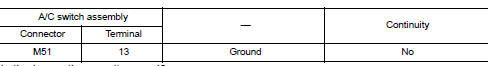
Is the inspection result normal? YES >> Perform trouble diagnosis for the A/C switch assembly. Refer to HAC-160, "A/C SWITCH ASSEMBLY : Diagnosis Procedure".
NO >> Repair harness or connector.
A/C ON SIGNAL
Component Function Check
1.Check a/c on signal
 With consult
- Turn ignition switch on.
- Operate blower motor.
- Select “AIR CONDITIONER” of “BCM” using CONSULT.
- Select “AIR COND SW” in “DATA MONITOR” mode.
- Check A/C ON signal when the A/C switch is operated.
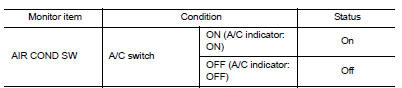
Is the inspection result normal? Yes >> inspection end.
No >> refer to hac-168, "diagnosis procedure".
Diagnosis Procedure
Regarding Wiring Diagram information, refer to HAC-145, "Wiring Diagram"
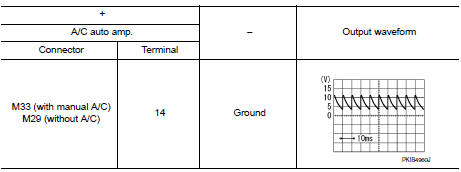
1.Check a/c on signal
- Turn ignition switch off.
- Disconnect a/c auto amp. Connector.
- Turn ignition switch ON
- Check output waveform between a/c auto amp. Harness connector and ground with using oscilloscope.
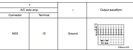
Is the inspection result normal? YES >> Replace A/C auto amp. Refer to HAC-189, "Removal and Installation".
NO >> GO TO 2.
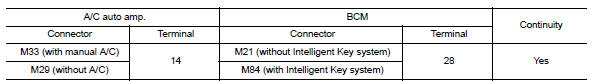
2.Check a/c on signal circuit for open
- Turn ignition switch off.
- Disconnect BCM connector.
- Check continuity between A/C auto amp. harness connector and BCM harness connector.
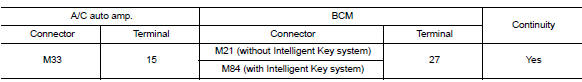
Is the inspection result normal? Yes >> go to 3.
No >> repair harness or connector.
3.Check a/c on signal circuit for short
Check continuity between a/c auto amp. Harness connector and ground.
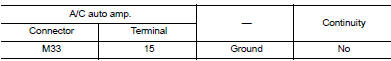
Is the inspection result normal? Yes >> replace bcm. Refer to bcs-73, "removal and installation" (with intelligent key system) or bcs- 126, "removal and installation" (without intelligent key system).
No >> repair harness or connector.
INTAKE SENSOR
Diagnosis Procedure
Regarding wiring diagram information, refer to hac-145, "wiring diagram".
1.Check intake sensor power supply
- Turn ignition switch OFF.
- Disconnect intake sensor connector.
- Turn ignition switch on.
- Check voltage between intake sensor harness connector and ground.
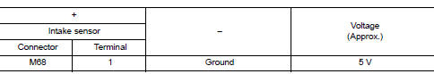
Is the inspection result normal? YES >> GO TO 2.
NO >> GO TO 4.
2.Check intake sensor ground circuit
- Turn ignition switch OFF.
- Check continuity between intake sensor harness connector and ground.
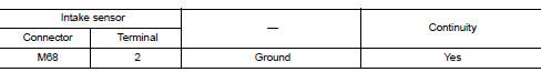
Is the inspection result normal? YES >> GO TO 3.
NO >> Repair harness or connector.
3.Check intake sensor
Check intake sensor. Refer to hac-171, "component inspection".
Is the inspection result normal? Yes >> replace a/c auto amp. Refer to hac-189, "removal and installation".
No >> replace intake sensor. Refer to hac-190, "removal and installation".
4.Check intake sensor power supply circuit for open
- Turn ignition switch off.
- Disconnect a/c auto amp. Connector.
- Check continuity between intake sensor harness connector and a/c auto amp. Harness connector.
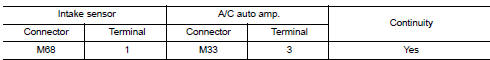
Is the inspection result normal? Yes >> go to 5.
No >> repair harness or connector.
5.Check intake sensor power supply circuit for short to ground
Check continuity between intake sensor harness connector and ground.
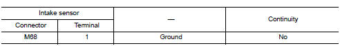
Is the inspection result normal? Yes >> go to 6.
No >> repair harness or connector.
6.Check intake sensor power supply circuit for short to voltage
- Turn ignition switch on.
- Check voltage between intake sensor harness connector and ground.
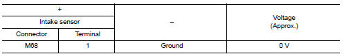
Is the inspection result normal? YES >> Replace A/C auto amp. Refer to HAC-189, "Removal and Installation".
NO >> Repair harness or connector.
Component Inspection
1.Check intake sensor
- Turn ignition switch OFF.
- Disconnect intake sensor connector.
- Check resistance between intake sensor terminals.
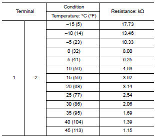
Is the inspection result normal? YES >> Inspection End.
NO >> Replace intake sensor. Refer to HAC-190, "Removal and Installation".
BLOWER FAN ON SIGNAL
Component Function Check
1.Check blower fan on signal
 With consult
Turn ignition switch on.
- Select “AIR CONDITIONER” of “BCM” using CONSULT.
- Select “FAN ON SIG” in “DATA MONITOR” mode
- Check blower fan on signal when the fan control dial is operated.
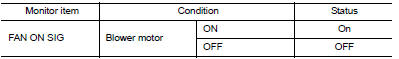
Is the inspection result normal? Yes >> inspection end.
No >> refer to hac-172, "diagnosis procedure".
Diagnosis Procedure
Regarding wiring diagram information, refer to hac-145, "wiring diagram" or hac-152, "wiring diagram".
1.Check blower fan on signal
- Turn ignition switch off.
- Disconnect a/c auto amp. Harness connector.
- Turn ignition switch on.
- Check output waveform between a/c auto amp. And ground with using oscilloscope.
Is the inspection result normal? Yes >> replace a/c auto amp. Refer to hac-189, "removal and installation".
No >> go to 2.
2.Check blower fan on signal circuit for ope
- Turn ignition switch off.
- Disconnect BCM connector.
- Check continuity a/c auto amp. Harness connector and bcm harness connector.
Is the inspection result normal? YES >> GO TO 3.
NO >> Repair harness or connector.
3.Check blower fan on signal circuit for short
Check continuity between a/c auto amp. Harness connector and ground.
Is the inspection result normal? Yes >> replace bcm. Refer to bcs-73, "removal and installation" (with intelligent key system) or bcs- 126, "removal and installation" (without intelligent key system).
No >> repair harness or connector.
BLOWER MOTOR
Diagnosis Procedure
Regarding wiring diagram information, refer to hac-145, "wiring diagram" or hac-152, "wiring diagram".
1.Check fuse
- Turn ignition switch OFF.
- Check following fuses.
- 10A fuse [No. 21, located in fuse block (J/B)]
- 15A fuses [Nos. 20 and 22, located in fuse block (J/B)]
Note:
Refer to pg-47, "terminal arrangement".
Is the inspection result normal? Yes >> go to 2.
No >> replace the blown fuse after repairing the affected circuit.
2.Check blower motor power supply
- Disconnect blower motor connector.
- Turn ignition switch on.
- Check voltage between blower motor harness connector and ground.
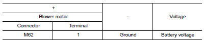
Is the inspection result normal? Yes >> go to 4.
No >> go to 3.
3.Check blower relay
- Turn ignition switch off.
- Check blower relay. Refer to hac-177, "component inspection (blower motor relay)".
Is the inspection result normal? YES >> Repair harness or connector between blower motor and fuse.
NO >> Replace blower relay.
4.Check blower motor control circuit
- Turn ignition switch off.
- Connect blower motor connector.
- Disconnect variable blower control connector.
- Turn ignition switch on.
- Check voltage between variable blower control harness connector and ground.
Is the inspection result normal? Yes >> go to 6.
No >> go to 5.
5.Check blower motor control circuit for open
- Turn ignition switch OFF.
- Disconnect blower motor connector.
- Check continuity between variable blower control harness connector and blower motor harness connector.
Is the inspection result normal? YES >> Replace blower motor. Refer to VTL-10, "Removal and Installation".
NO >> Repair harness or connector.
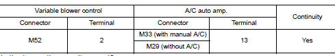
6.Check a/c auto amp. Ignition power supply
- Turn ignition switch off.
- Disconnect a/c auto amp.
- Turn ignition switch ON.
- Check voltage between a/c auto amp. Harness connector and ground.
Is the inspection result normal? Yes >> go to 7.
No >> repair harness or connector between a/c auto amp. And fuse.
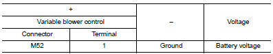
7.Check variable blower control ignition power supply
Check voltage between variable blower control harness connector and ground.
Is the inspection result normal? Yes >> go to 8.
No >> repair harness or connector between variable blower control and fuse.
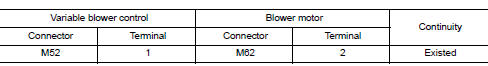
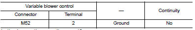
8.Check variable blower control ground circuit for open
- Turn ignition switch off.
- Check continuity between variable blower control harness connector and ground.
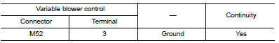
Is the inspection result normal? Yes >> go to 9.
No >> repair harness or connector.
9.Check variable blower control control signal
- Connect variable blower control connector and a/c auto amp. Connector.
- Turn ignition switch ON.
- Set air outlet to VENT.
- Change fan speed from 1st – 7th, and check duty ratios between variable blower control harness connector and ground by using an oscilloscope.
Note:
Calculate the drive signal duty ratio as shown in the figure.
T2 = approx. 1.6 Ms
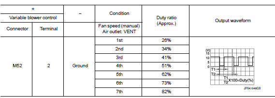
Is the inspection result normal? YES >> Replace variable blower control. Refer to HAC-194, "Removal and Installation".
NO >> GO TO 10.
10.Check variable blower control control signal circuit for open
- Turn ignition switch OFF.
- Disconnect variable blower control connector and A/C auto amp. connector.
- Check continuity between variable blower control harness connector and a/c auto amp. Harness connector.
Is the inspection result normal? Yes >> go to 11.
No >> repair harness or connector.
11.Check variable blower control control signal circuit for short
Check continuity between variable blower control harness connector and ground.
Is the inspection result normal? YES >> Replace A/C auto amp. Refer to HAC-189, "Removal and Installation".
NO >> Repair harness or connector.
Component Inspection (Blower Motor)
1.Check blower motor
- Connect battery voltage to terminal 1 of blower motor.
- Connect ground to terminal 2 of blower motor.
Does the blower fan operate? Yes >> intermittent incident. Refer to gi-39, "intermittent incident".
NO >> Replace blower motor. Refer to VTL-10, "Removal and Installation".
Component Inspection (Blower Motor Relay)
1.Check blower relay
- Turn ignition switch off.
- Remove blower motor relay.
- Check continuity between blower motor relay terminals 3 and 5 when voltage is supplied between terminals 1 and 2.
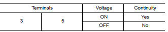
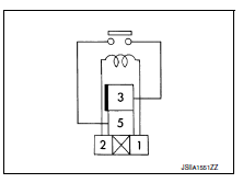
Is the inspection result normal? Yes >> inspection end.
No >> replace blower motor relay.
MAGNET CLUTCH
Component Function Check
1.Check magnet clutch operation
Perform auto active test of IPDM E/R. Refer to PCS-9, "Diagnosis Description" (with Intelligent Key system) or PCS-37, "Diagnosis Description" (without Intelligent Key system).
Does it operate normally? YES >> Inspection End.
NO >> Refer to HAC-178, "Diagnosis Procedure".
Diagnosis Procedure
Regarding wiring diagram information, refer to hac-145, "wiring diagram".
1.CHECK FUSE
- Turn ignition switch OFF.
- Check 10A fuse (No. 39, located in IPDM E/R).
NOTE:
Refer to PG-49, "IPDM E/R Terminal Arrangement".
Is the inspection result normal? YES >> GO TO 2.
NO >> Replace the blown fuse after repairing the affected circuit.
2.Check magnet clutch power supply circuit
- Disconnect compressor connector and IPDM E/R connector.
- Check continuity between compressor harness connector and IPDM E/R harness connector.
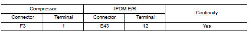
Is the inspection result normal? YES >> GO TO 3.
NO >> Repair harness or connector.
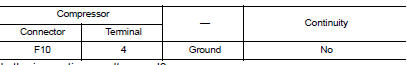
3.Check magnet clutch ground circuit
- Disconnect compressor connector.
- Check continuity between compressor harness connector and ground.
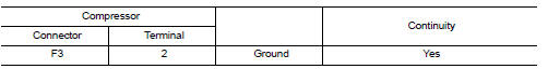
Is the inspection result normal? Yes >> go to 4.
No >> repair harness or connector.
4.Check magnet clutch
Directly apply battery voltage to the magnet clutch. Check operation visually and by sound.
Does it operate normally? YES >> Replace IPDM E/R. Refer to PCS-30, "Removal and Installation" (with Intelligent Key system) or PCS-58, "Removal and Installation" (without Intelligent Key system).
NO >> Replace magnet clutch. Refer to HA-31, "MAGNET CLUTCH : Removal and Installation".
ECV (ELECTRICAL CONTROL VALVE)
Diagnosis Procedure
Regarding wiring diagram information, refer to hac-145, "wiring diagram".
1.Check ecv (electrical control valve) power supply
- Turn ignition switch off
- Disconnect compressor connector.
- Turn ignition switch ON.
- Check voltage between compressor harness connector and ground.
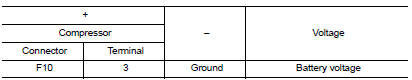
Is the inspection result normal? YES >> GO TO 3.
NO >> GO TO 2.
2.Check fuse
- Turn ignition switch off.
- Check 10 a fuse [no. 5, Located in fuse block (j/b)]. Refer to pg-47, "terminal arrangement"
Is the inspection result normal? YES >> Repair harness or connector.
NO >> Replace the blown fuse after repairing the affected circuit.
3.Check ecv control signal circuit for open
- Turn ignition switch off
- Disconnect a/c auto amp. Connector.
- Check continuity between compressor harness connector and a/c auto amp. Harness connector.
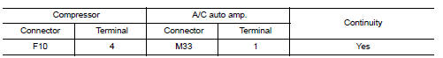
Is the inspection result normal? YES >> GO TO 4.
NO >> Repair harness or connector.
4.Check ecv control signal circuit for short
Check continuity between compressor harness connector and ground.
Is the inspection result normal? YES >> GO TO 5.
NO >> Repair harness or connector.
5.Check ecv
Check ECV. Refer to HAC-180, "Component Inspection".
Is the inspection result normal? Yes >> go to 6.
No >> replace compressor. Refer to ha-31, "compressor : removal and installation".
6.Check intermittent incident
Refer to gi-39, "intermittent incident".
Is the inspection result normal? Yes >> replace a/c auto amp. Refer to hac-189, "removal and installation".
No >> repair or replace malfunctioning parts.
Component Inspection
1.Check ecv (electrical control valve)
- Turn ignition switch OFF.
- Disconnect compressor connector.
- Check continuity between compressor connector F88 terminals
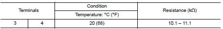
Is the inspection result normal? YES >> Inspection End.
NO >> Replace compressor. Refer to HA-31, "COMPRESSOR : Removal and Installation".
 Basic inspection
DIAGNOSIS AND REPAIR WORKFLOW
Work Flow
DETAILED FLOW
1.LISTEN TO CUSTOMER COMPLAINT
Listen to customer complaint. Get detailed information about the conditions
and environment when the symptom
...
 Symptom diagnosis
HEATER AND AIR CONDITIONING SYSTEM
CONTROL SYMPTOMS
Symptom Table
INSUFFICIENT COOLING
Component Function Check
Symptom: insufficient cooling
Inspection flow
1. Confirm symptom by performin ...
Other materials:
Warning signals
To help prevent the vehicle from moving unexpectedly
by erroneous operation of the Intelligent
Key or to help prevent the vehicle from being
stolen, a chime or buzzer sounds from inside and
outside the vehicle and a warning light comes on
in the instrument panel.
When a chime or beep sounds ...
Engine Oils
Prolonged and repeated contact with used engine oil may cause skin cancer.
Try to avoid direct skin contact
with used oil.
If skin contact is made, wash thoroughly with soap or hand cleaner as soon as
possible.
HEALTH PROTECTION PRECAUTIONS
Avoid prolonged and repeated contact with oils ...
Precaution for Harness Repair
Solder the repair part, and wrap it with tape. [Twisted wire
fray
must be 110 mm (4.33 in) or less.]
Do not bypass the repair point with wire. (If it is
bypassed, the turnout
point cannot be separated and the twisted wire characteristics
are lost.)
...
