Nissan Sentra Service Manual: Diagnosis system (combination meter)
Description
COMBINATION METER SELF-DIAGNOSIS MODE
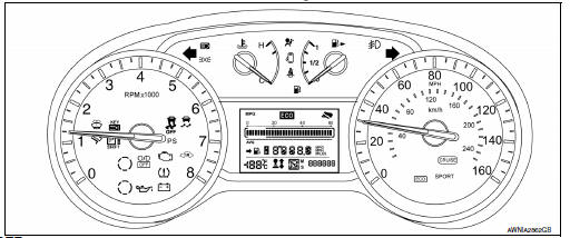
The information display, speedometer and tachometer can be checked in self-diagnosis mode.
STARTING COMBINATION METER SELF-DIAGNOSIS MODE
NOTE:
- Check combination meter power supply and ground circuits if self-diagnosis mode does not start. Refer to MWI-52, "COMBINATION METER : Diagnosis Procedure". Replace combination meter if power supply and ground circuits are found to be normal and self-diagnosis mode does not start. Refer to MWI-77, "Removal and Installation".
- Combination meter self-diagnosis mode will function with the ignition switch in ON. Combination meter selfdiagnosis mode will exit upon turning the ignition switch to OFF.
How to Initiate Self-Diagnosis Mode
- Turn ignition switch OFF.
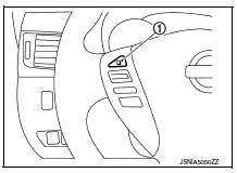
- While pressing the steering switch 1 , turn ignition switch ON.
- If the diagnosis function is activated with “trip A” displayed, the mileage on “trip A” is reset to “0000.0”. (The same way for “trip B”.)
- Make sure that the trip meter displays “0000.0”.
- Press the steering switch 1 at least 3 times. (Within 7 seconds after the ignition switch is turned ON.)
- The combination meter is turned to self-diagnosis mode.
- Speedometer, tachometer, engine coolant temperature gauge, fuel gauge, and return to zero, simultaneously.
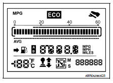
- All segments of the information display are displayed.
NOTE:
- Check the following items when the self-diagnosis mode of the
combination meter does not start.
Replace combination meter if the following items are normal.
- Combination meter power supply and ground circuit.
- Steering switch signal circuit and steering switch.
- If any of the dots are not displayed, replace combination meter.
- Each meter activates by pressing the steering switch .
NOTE:
- If any of the meters or gauges is not activated, replace combination meter.
- The figure is reference.
Consult function (meter/m&a)
APPLICATION ITEMS
CONSULT can perform the following diagnosis modes via CAN communication and the combination meter.
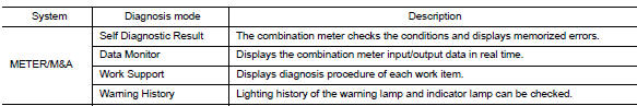
SELF DIAG RESULT
Refer to MWI-26, "DTC Index".
DATA MONITOR
Display Item List
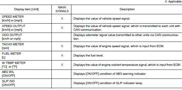
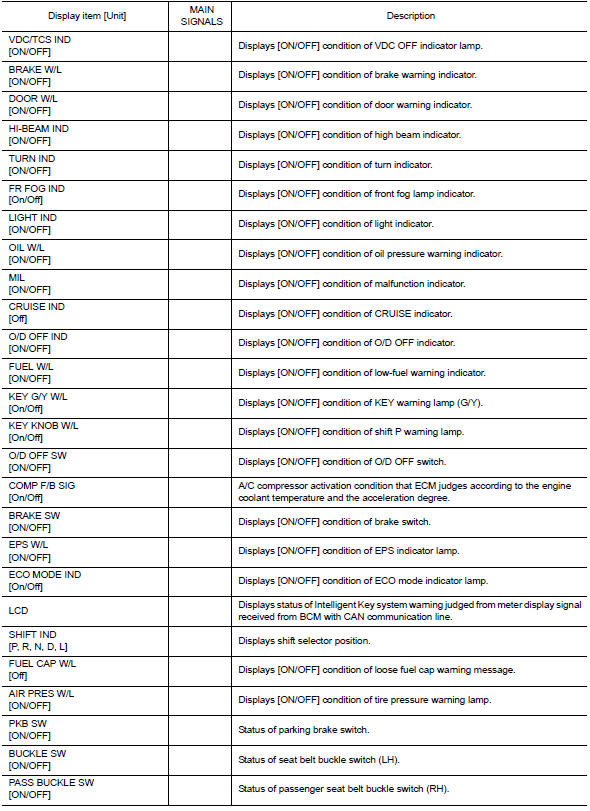
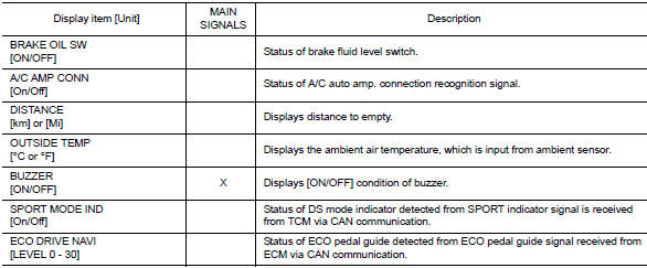
NOTE:
Some items are not available according to vehicle specification.
WARNING HISTORY
- Stores histories when warning/indicator lamp is turned on.
- “WARNING HISTORY” indicates the “TIME” when the warning/ indicator lamp is turned on.
- The “TIME” above is:
- 0: The condition that the warning/indicator lamp has been turned on 1 or more times after starting the engine and waiting for 30 seconds.
- 1 - 39: The number of times the engine was restarted after the 0 condition.
- NO WARNING HISTORY: Stores NO (0) turning on history of warning/indicator lamp.
NOTE:
- WARNING HISTORY is not stored for approximately 30 seconds after the engine starts.
- Brake warning lamp does not store any history when the parking brake is applied or the brake fluid level gets low.
WORK SUPPORT
| Work support item | Description |
| Turn signal buzzer diagnosis | A possible malfunction can be narrowed down by following displayed instructions. |
| Outside air temperature diagnosis | |
| Fuel meter diagnosis (Analog pointer) | |
| Warning/Indicator lamp diagnosis |
 System
Meter system
Meter system : system diagram
Meter system : system description
COMBINATION METER
The combination meter receives signals from switches, sensors and modules to
control the foll ...

Other materials:
Precaution
Precaution for supplemental restraint system (srs) "air bag" and "seat belt
pre-tensioner"
The Supplemental Restraint System such as “AIR BAG” and “SEAT BELT PRE-TENSIONER”,
used along
with a front seat belt, helps to reduce the risk or severity of injur ...
Roof side molding
Exploded view
Roof side molding
Roof side molding clip
Roof panel
Body side outer panel
Adhesive tape
Removal and installation
REMOVAL
ROOF SIDE MOLDING
Release roof side molding rear side clip, using a suitable tool
(A).
Clip
Front
CAUTION:
Apply protective tape ...
Wiring diagram
Rear window defogger system
Wiring diagram
...
