Nissan Sentra Service Manual: Brake pedal
Exploded View
WITHOUT BRAKE PEDAL POSITION SWITCH
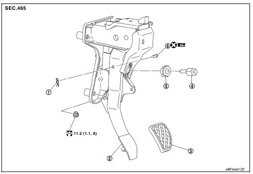
- Snap pin
- Brake pedal assembly
- Brake pedal pad
- Stop lamp switch
- Clip
- Clevis pin
 Apply multi-purpose grease.
WITH BRAKE PEDAL POSITION SWITCH
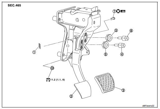
- Snap pin
- Brake pedal assembly
- Brake pedal pad
- Brake pedal position switch
- Clip
- Stop lamp switch
 Apply multi-purpose grease.
Removal and Installation
REMOVAL
- Remove instrument lower panel LH. Refer to IP-21, "Removal and Installation".
- Remove steering column lower cover. Refer to IP-16, "Removal and Installation".
- Disconnect the harness connectors from the brake pedal position switch (if equipped) and the stop lamp switch.
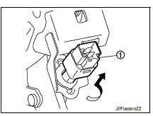
- Rotate the stop lamp switch and the brake pedal position switch (if equipped) (1) counter clockwise to remove.
- Disconnect the accelerator pedal harness connector and harness clip.
- Remove snap pin and clevis pin from clevis on brake booster.
- Remove the brake pedal assembly.
CAUTION:
Secure the brake booster and brake master cylinder to avoid damage to components.
- Remove accelerator pedal from brake pedal assembly. Refer to ACC-3, "Removal and Installation".
INSPECTION AFTER REMOVAL
Check for the following items and replace the brake pedal assembly, if necessary.
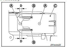
- Check the brake pedal upper rivet (A) for damage or wear.
- Check the brake pedal for bend, damage, and cracks on the welded parts.
- Check the lapping length (D) of sub-bracket (B) and slide plate (C).
Lapping length (D) : 6.5 mm (0.256 in) or more
INSTALLATION
Installation is in the reverse order of removal.
CAUTION:
- Do not reuse the clevis pin.
- Install the clevis pin in the proper direction. Refer to BR-22, "Exploded View".
- Apply multi-purpose grease to the clevis pin and the mating faces, if necessary.
ADJUSTMENT AFTER INSTALLATION
- Adjust each item of brake pedal after installing the brake pedal assembly to the vehicle. Refer to BR-15, "Adjustment".
- Perform the release position learning of the accelerator pedal. Refer to EC-138, "Work Procedure".

 Brake piping
FRONT
FRONT : Exploded View
Brake tube
ABS actuator and electric unit (control
unit)
Connector
Connector bracket
Master cylinder assembly
Brake booster
Lock plate
Brake hose
...
Other materials:
Ecm branch line circuit
Diagnosis procedure
1.Check connector
Turn the ignition switch off.
Disconnect the battery cable from the negative terminal.
Check the terminals and connectors of the ecm for damage, bend and loose
connection (unit side and
connector side).
Is the inspection result normal?
Yes > ...
Push-Button Ignition Switch (if so equipped)
WARNINGDo not operate the push-button ignition
switch while driving the vehicle except in
an emergency. (The engine will stop when
the ignition switch is pushed 3 consecutive
times in quick succession or the ignition
switch is pushed and held for more
than 2 seconds.) If ...
Component parts
Component Parts Location
Driver air bag module
Front passenger air bag off indicator
Front passenger air bag module
Front LH side air bag module
(RH similar)
LH side curtain air bag module
(view with headliner removed)
(RH similar)
Front LH seatbelt pre-tensioner
(view wit ...
