Nissan Sentra Service Manual: Brake master cylinder
Exploded View
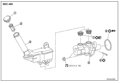
- Reservoir cap
- Oil strainer
- Reservoir tank
- Cylinder body
- Pin
- O-ring
- Grommet
 Apply brake fluid
 PBC (Poly Butyl Cuprysil)
grease or
silicone-based grease
Removal and Installation
REMOVAL
CAUTION:
- Do not spill or splash brake fluid on painted surfaces. Brake fluid may damage paint. If brake fluid is splashed on painted areas, wash it away with water immediately.
- Do not scratch the piston of master cylinder when installing/removing because the piston is exposed. Check for any dust on the piston, and wash with brake fluid if needed.
- Hold the master cylinder body when handing the master cylinder assembly. Do not hold the piston because the piston might become detached if pulled strongly.
- Refill the reservoir tank with new brake fluid “DOT 3”.
- Do not reuse drained brake fluid.
- Do not reuse master cylinder O-ring.
NOTE:
When removing components such as hoses, tubes/lines, etc., cap or plug openings to prevent fluid from spilling.
- Partially drain brake fluid. Refer to BR-17, "Drain and Refill".
- Disconnect the harness connector from the brake fluid level switch.
- Remove air duct and air cleaner case. Refer to EM-25, "Removal and Installation".
- Remove the engine room insulator and position aside.
- Separate the brake tube from master cylinder assembly with a suitable tool.
CAUTION:
Do not scratch the flare nut and the brake tube.
- Disconnect the clutch hose (if equipped).
- Remove the master cylinder assembly.
CAUTION:
- Do not deform or bend the brake tubes.
- Do not depress the brake pedal after the master cylinder assembly is removed.
- The piston of the master cylinder assembly is exposed. Do not damage the piston when removing the master cylinder.
- The piston may drop off when pulled out strongly. Do not hold the piston. Hold the cylinder body when handling the master cylinder assembly.
- Remove and discard the O-ring.
CAUTION:
Do not reuse O-ring.
INSTALLATION
Installation is in the reverse order of removal.
CAUTION:
Do not reuse O-ring.
- Apply PBC (Poly Butyl Cuprysil) grease or equivalent to the brake booster (A) when installing the master cylinder assembly to the brake booster.
- Temporarily tighten the brake tube flare nut to the master cylinder assembly by hand. Then tighten it to the specified torque.Refer to BR-25, "FRONT : Exploded View".
- Perform the air bleeding. Refer to BR-17, "Bleeding Brake System".
 Brake piping
FRONT
FRONT : Exploded View
Brake tube
ABS actuator and electric unit (control
unit)
Connector
Connector bracket
Master cylinder assembly
Brake booster
Lock plate
Brake hose
...
 Brake booster
Exploded View
Master cylinder assembly
Brake booster
Lock nut
Clevis
Gasket
Spacer
Removal and installation
REMOVAL
Remove cowl top and cowl top extension. Refer to EXT-26, ...
Other materials:
C1604 Torque sensor
DTC Logic
DTC DETECTION LOGIC
DTC
Display item
Malfunction detected condition
Possible cause
C1604
TORQUE SENSOR
When torque sensor output signal is malfunctioning
Harness or connector
Torque sensor
EPS control unit
DTC CONFIRMATION ...
Cleaning
If your windshield is not clear after using the
windshield washer or if a wiper blade chatters
when running, wax or other material may be on
the blade or windshield.
Clean the outside of the windshield with a washer
fluid or a mild detergent. Your windshield is clean
if beads do not form whe ...
Push-button ignition switch positions
LOCK (Normal parking position):
The ignition switch can only be locked in this
position.
The ignition switch will be unlocked when it is
pushed to the ACC position while carrying the
Intelligent Key or with the Intelligent Key inserted
in the port.
The ignition switch will lock when any d ...
