Nissan Sentra Service Manual: Basic inspection
Diagnosis and repair workflow
Work Flow (With GR8-1200 NI)
STARTING SYSTEM DIAGNOSIS WITH GR8-1200 NI
To test the starting system, use the following special service tool:
- GR8-1200 NI Multitasking battery and electrical diagnostic station
NOTE:
Refer to the diagnostic station Instruction Manual for proper starting system diagnosis procedures.
OVERALL SEQUENCE
DETAILED FLOW
NOTE:
To ensure a complete and thorough diagnosis, the battery, starter motor and generator test segments must be done as a set from start to finish.
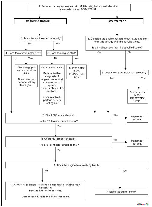
1.DIAGNOSIS WITH MULTITASKING BATTERY AND ELECTRICAL DIAGNOSTIC STATION GR8-1200 NI
Perform the starting system test with Multitasking battery and electrical diagnostic station GR8-1200 NI. For details and operating instructions, refer to diagnostic station Instruction Manual.
Test result
CRANKING NORMAL>>GO TO 2.
LOW VOLTAGE>>GO TO 5.
CHARGE BATTERY>>Perform the slow battery charging procedure. (Initial rate of charge is 10A for 12 hours.) Perform battery test again. Refer to diagnostic station instruction manual.
REPLACE BATTERY>>Before replacing battery, clean the battery cable clamps and battery posts. Perform battery test again. Refer to diagnostic station instruction manual. If second test result is “REPLACE BATTERY”, then do so. Perform battery test again to confirm repair.
2.CRANKING CHECK
Check that the starter motor operates properly.
Does the engine crank normally? YES >> GO TO 3.
NO >> GO TO 4.
3.ENGINE START CHECK
Check that the engine starts.
Does the engine start? YES >> Inspection End.
NO >> Perform further diagnosis of engine mechanical or engine control system. Refer to EM and EC sections. Once resolved, perform battery test again.
4.STARTER MOTOR ACTIVATION
Check that the starter motor operates.
Does the starter motor turn? YES >> Check ring gear and starter motor drive pinion. Once resolved, perform battery test again.
NO >> GO TO 7.
5.COMPARISON BETWEEN ENGINE COOLANT AND CRANKING VOLTAGE
Compare the engine coolant temperature and verify the cranking voltage is within specifications.
Minimum Specification of Cranking Voltage Referencing Coolant Temperature
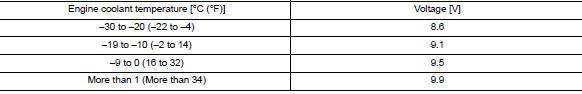
Is the voltage less than the specified value? YES >> GO TO 7.
NO >> GO TO 6.
6.STARTER OPERATION
Check the starter operation.
Does the starter motor turn smoothly? YES >> Inspection End.
NO >> GO TO 7.
7.“B” TERMINAL CIRCUIT INSPECTION
Check “B” terminal circuit. Refer to STR-26, "Diagnosis Procedure".
Is “B” terminal circuit normal? YES >> GO TO 8.
NO >> Repair as needed.
8.“S” CONNECTOR CIRCUIT INSPECTION
Check “S” connector circuit. Refer to STR-28, "Diagnosis Procedure".
Is “S” connector circuit normal? YES >> GO TO 9.
NO >> Repair as needed.
9.ENGINE ROTATION STATUS
Check that the engine can be rotated by hand.
Does the engine turn freely by hand? YES >> Replace starter motor.
NO >> Perform further diagnosis of engine mechanical or powertrain mechanism. Once resolved, perform battery test again using Multitasking battery and electrical diagnostic station GR8-1200 NI.
Refer to the diagnostic station Instruction Manual for proper testing procedures.
Work Flow (Without GR8-1200 NI)
 Starting system (without intelligent key)
Wiring Diagram
...

Other materials:
BCM branch line circuit
Diagnosis procedure
1.Check connector
Turn the ignition switch off.
Disconnect the battery cable from the negative terminal.
Check the terminals and connectors of the bcm for damage, bend and loose
connection (unit side and
connector side).
Is the inspection result normal?
Yes > ...
Corrosion protection
Description
To provide improved corrosion prevention, the following anti-corrosive
measures have been implemented in
NISSAN production plants. When repairing or replacing body panels, it is
necessary to use the same anti-corrosive
measures.
Anti-Corrosive Wax
To improve repairability and co ...
Power generation voltage variable control system
System Diagram
System Description
Power generation variable voltage control system has been adopted. By varying
the voltage to the generator,
engine load due to power generation of the generator is reduced and fuel
consumption is decreased.
NOTE:
When any malfunction is detected in the ...
