Nissan Sentra Service Manual: Basic inspection
Diagnosis and repair workflow
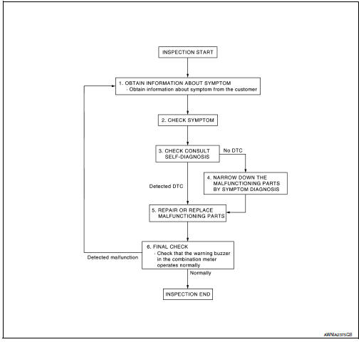
Work flow
Overall sequence
Detailed flow
1.Obtain information about symptom
Interview the customer to obtain as much information as possible about the conditions and environment under which the malfunction occurred.
>> GO TO 2.
2.Check symptom
- Check the symptom based on the information obtained from the customer.
- Check if any other malfunctions are present.
>> Go to 3.
3.Check consult self-diagnosis results
Connect consult and perform self-diagnosis. Refer to mwi-26, "dtc index".
Are self-diagnosis results normal? Yes >> go to 4.
No >> go to 5.
4.Narrow down malfunctioning parts by symptom diagnosis
Perform symptom diagnosis and narrow down the malfunctioning parts.
>> Go to 5.
5.Repair or replace malfunctioning parts
Repair or replace malfunctioning parts.
Note:
If dtc is displayed, erase dtc after repairing or replacing malfunctioning parts.
>> Go to 6.
6.Final check
Check that the warning buzzer in the combination meter operates normally.
Does it operate normally? Yes >> inspection end.
No >> go to 1.
 Wiring diagram
Meter system
Wiring diagram
Compass
Wiring diagram
...

Other materials:
System description
Component parts
Component parts location
Ipdm e/r (contains ignition relay-1)
Bcm (view with instrument panel removed)
Fuse block (j/b) (front)
Fuse block (j/b) (back)
Blower relay
Ignition relay-2
Accessory relay-1
Push-button ignition switch
Component description
...
P0130 A/F Sensor 1
DTC Logic
DTC DETECTION LOGIC
To judge the malfunction, the diagnosis checks that the A/F signal computed
by ECM from the A/F sensor 1
signal fluctuates according to fuel feedback control.
DTC No.
CONSULT screen terms
(Trouble diagnosis content)
DTC detecting condition
Possi ...
Removal and installation
Audio unit
Exploded view
Audio unit
Audio unit bracket (LH)
Audio unit bracket (rh)
Removal and installation
Removal
Disconnect the negative battery terminal. Refer to pg-50, "removal and
installation (battery)".
Remove cluster lid c lower. Refer to ip-20, "re ...
