Nissan Sentra Service Manual: Basic inspection
Diagnosis and repair workflow
Work Flow
OVERALL SEQUENCE
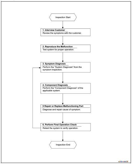
DETAILED FLOW
1. OBTAIN INFORMATION ABOUT SYMPTOM
Interview the customer to obtain as much information as possible about the conditions and environment under which the malfunction occurred.
>> GO TO 2.
2. CONFIRM THE SYMPTOM
Check the malfunction on the vehicle that the customer describes.
Inspect the relation of the symptoms and the condition when the symptoms occur.
>> GO TO 3.
3. IDENTIFY THE MALFUNCTIONING SYSTEM WITH SYMPTOM DIAGNOSIS
Use Symptom diagnosis from the symptom inspection result in step 2 and then identify where to start performing the diagnosis based on possible causes and symptoms. Refer to WW-46, "Symptom Table".
>> GO TO 4.
4. PERFORM THE COMPONENT DIAGNOSIS OF THE OF THE APPLICABLE SYSTEM
Perform the diagnosis with Component diagnosis of the applicable system.
>> GO TO 5.
5. REPAIR OR REPLACE THE MALFUNCTIONING PARTS
Repair or replace the specified malfunctioning parts.
>> GO TO 6.
6. FINAL CHECK
Check that malfunctions are not reproduced when obtaining the malfunction information from the customer, referring to the symptom inspection result in step 2.
Are the malfunctions corrected? YES >> Inspection End.
NO >> GO TO 3.
 Wiring diagram
Wiper and washer system
Wiring diagram - with intelligent key
Wiring diagram - without intelligent key
...

Other materials:
P050A, P050B, P050E Cold start control
Description
ECM controls ignition timing and engine idle speed when engine is started
with pre-warming up condition.
This control promotes the activation of three way catalyst by heating the
catalyst and reduces emissions.
DTC Logic
DTC DETECTION LOGIC
NOTE:
If DTC P050A, P050B or P050E ...
System
System Description
Operation description
A/C control transmits rear window defogger switch signal to A/C auto
amp. when rear window defogger
switch turns ON while ignition switch is ON.
A/C auto amp. transmits rear window defogger switch signal to BCM
Bcm transmits rear window defogg ...
Evap canister
Exploded View
EVAP canister bracket
EVAP canister filter drain hose
EVAP canister filter
EVAP canister protector
EVAP hose
EVAP canister vent control valve
O-ring
EVAP canister
O-ring
EVAP canister control pressure sensor
Clip
Nut
Removal and Installation
EVAP ...
