Nissan Sentra Service Manual: P0963 Pressure control solenoid A
DTC Logic
DTC DETECTION LOGIC
| DTC | CONSULT screen terms (Trouble diagnosis content) | DTC detection condition | Possible causes |
| P0963 | PC SOLENOID A (Pressure Control Solenoid A Control Circuit High) | The line pressure solenoid valve current is 200
mA or less continuously for 200 msec or more
under the following diagnosis conditions: Diagnosis conditions
|
|
DTC CONFIRMATION PROCEDURE
1.PREPARATION BEFORE WORK
If another “DTC CONFIRMATION PROCEDURE” occurs just before, turn ignition switch OFF and wait for at least 10 seconds, then perform the next test.
>> GO TO 2.
2.CHECK DTC DETECTION
- Start the engine and wait for 5 seconds or more.
- Check the first trip DTC.
Is “P0963” detected? YES >> Go to TM-203, "Diagnosis Procedure".
NO >> INSPECTION END
Diagnosis Procedure
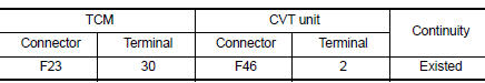
1.CHECK CIRCUIT BETWEEN TCM AND CVT UNIT
- Turn ignition switch OFF.
- Disconnect TCM connector and CVT unit connector.
- Check continuity between TCM harness connector terminal and CVT unit harness connector terminal.
Is the inspection result normal? YES >> GO TO 2.
NO >> Repair or replace malfunctioning parts.
2.CHECK LINE PRESSURE SOLENOID VALVE
Check line pressure solenoid valve. Refer to TM-203, "Component Inspection".
Is the inspection result normal? YES >> Check intermittent incident. Refer to GI-39, "Intermittent Incident".
NO >> Repair or replace malfunctioning parts.
Component Inspection
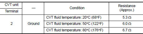
1.CHECK LINE PRESSURE SOLENOID VALVE
Check resistance between CVT unit connector terminal and ground.
 Is the inspection
result normal?
YES >> INSPECTION END
NO >> There is a malfunction of line pressure solenoid valve. Replace transaxle assembly. Refer to TM- 283, "Removal and Installation".
 P0962 Pressure control solenoid A
DTC Logic
DTC DETECTION LOGIC
DTC
CONSULT screen terms
(Trouble diagnosis content)
DTC detection condition
Possible causes
P0962
PRESSURE CONTROL SOLENOID
A
(Pre ...
 P0965 Pressure control solenoid B
DTC Logic
DTC DETECTION LOGIC
DTC
CONSULT screen terms
(Trouble diagnosis content)
DTC detection condition
Possible causes
P0965
PC SOLENOID B
(Pressure control sol ...
Other materials:
Floor mats
WARNING
To avoid potential pedal interference that
may result in a collision or injury:
NEVER place a floor mat on top of another
floor mat in the driver front
position.
Use only genuine NISSAN floor mats
specifically designed for use in your vehicle
model. See ...
Symptom diagnosis
Audio system
Symptom table
Related to audio
Related to hands-free phone
Before performing diagnosis, confirm that the cellular phone being used
by the customer is compatible with
the vehicle.
It is possible that a malfunction is occurring due to a version change
of the phone ...
Types of tires
WARNING
When changing or replacing tires, be
sure all four tires are of the same type
(i.e., Summer, All Season or Snow) and
construction. A NISSAN dealer may be
able to help you with information about
tire type, size, speed rating and
availability.
Replacement ...
