Nissan Sentra Service Manual: Abs branch line circuit
Diagnosis Procedure
1.Check connector
- Turn the ignition switch off.
- Disconnect the battery cable from the negative terminal.
- Check the terminals and connectors of the abs actuator and electric unit (control unit) for damage, bend and loose connection (unit side and connector side).
Is the inspection result normal? Yes >> go to 2.
No >> repair the terminal and connector.
2.Check harness for open circuit
- Disconnect the connector of abs actuator and electric unit (control unit).
- Check the resistance between the abs actuator and electric unit (control unit) harness connector terminals.
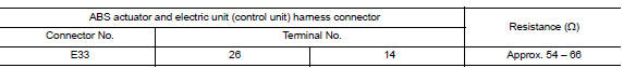
Is the measurement value within the specification? Yes >> go to 3.
No >> repair the abs actuator and electric unit (control unit) branch line.
3.Check power supply and ground circuit
Check the power supply and the ground circuit of the abs actuator and electric unit (control unit). Refer to brc-62, "diagnosis procedure".
Is the inspection result normal? Yes (present error)>>replace the abs actuator and electric unit (control unit). Refer to brc-110, "removal and installation".
Yes (past error)>>error was detected in the abs actuator and electric unit (control unit) branch line.
No >> repair the power supply and the ground circuit.
 Ecm branch line circuit
Diagnosis procedure
1.Check connector
Turn the ignition switch off.
Disconnect the battery cable from the negative terminal.
Check the terminals and connectors of the ecm for damage, bend and ...
 Ipdm-e branch line circuit
Diagnosis procedure
1.Check connector
Turn the ignition switch OFF.
Disconnect the battery cable from the negative terminal.
Check the terminals and connectors of the ipdm e/r for damage, ben ...
Other materials:
The key warning does not sound
(without intelligent key)
Description
The key warning chime does not sound, when all of the following conditions
are fulfilled.
Key inserted into the key cylinder (key switch signal on).
Ignition switch is in acc or off (ignition switch signal off).
Driver side door is open (driver side door switch on)
Diagnosi ...
P0116 ECT Sensor
DTC Logic
DTC DETECTION LOGIC
DTC No.
CONSULT screen terms
(Trouble diagnosis content)
DTC detecting condition
Possible cause
P0116
ECT SEN/CIRC
(Engine coolant temperature
sensor 1 circuit range/performance)
The comparison result of signals transmitted
t ...
Service Notice or Precautions for Steering System
In case of removing steering gear assembly, make the final
tightening with grounded and unloaded vehicle
condition, and then check wheel alignment.
Observe the following precautions when disassembling.
Before disassembly, thoroughly clean the outside of the
unit.
...
