Nissan Sentra Service Manual: Abs branch line circuit
Diagnosis procedure
1.Check connector
- Turn the ignition switch OFF.
- Disconnect the battery cable from the negative terminal.
- Check the terminals and connectors of the abs actuator and electric unit (control unit) for damage, bend and loose connection (unit side and connector side).
Is the inspection result normal? Yes >> go to 2.
No >> repair the terminal and connector.
2.Check harness for open circuit
- Disconnect the connector of abs actuator and electric unit (control unit).
- Check the resistance between the abs actuator and electric unit (control unit) harness connector terminals.
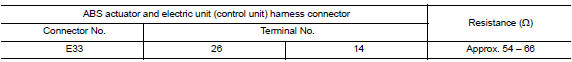
Is the measurement value within the specification? Yes >> go to 3.
No >> repair the abs actuator and electric unit (control unit) branch line.
3.Check power supply and ground circuit
Check the power supply and the ground circuit of the abs actuator and electric unit (control unit). Refer to brc-62, "diagnosis procedure".
Is the inspection result normal? Yes (present error)>>replace the abs actuator and electric unit (control unit). Refer to brc-110, "removal and installation".
Yes (past error)>>error was detected in the abs actuator and electric unit (control unit) branch line.
No >> repair the power supply and the ground circuit.
 Ecm branch line circuit
Diagnosis procedure
1.Check connector
Turn the ignition switch off.
Disconnect the battery cable from the negative terminal.
Check the terminals and connectors of the ecm for damage, bend and ...
 Ipdm-e branch line circuit
Diagnosis procedure
1.Check connector
Turn the ignition switch OFF.
Disconnect the battery cable from the negative terminal.
Check the terminals and connectors of the IPDM E/R for damage, ben ...
Other materials:
Diagnosis system (BCM)
Common item
COMMON ITEM : CONSULT Function (BCM - COMMON ITEM)
Application item
Consult performs the following functions via can communication with bcm.
System application
BCM can perform the following functions.
Door lock
Door lock : consult function (bcm - door lock)
Data monitor
...
Wiring diagram
Base audio
Wiring diagram
...
Hazard warning flasher switch
Push the switch on to warn other drivers when
you must stop or park under emergency conditions.
All turn signal lights flash.
WARNING
If stopping for an emergency, be sure to
move the vehicle well off the road.
Do not use the hazard warning flashers
while moving on th ...
