Nissan Sentra Service Manual: 6M/T
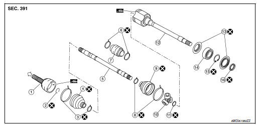
6M/T : Exploded View (LH)
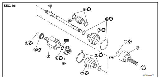
- Circular clip
- Dust shield
- Slide joint housing
- Snap ring
- Spider assembly
- Boot band
- Boot
- Shaft
- Damper band
- Dynamic damper
- Circular clip
- Joint sub-assembly
 Wheel side
6M/T : Disassembly and Assembly (LH)
DISASSEMBLY (WHEEL SIDE)
CAUTION:
When mounting the drive shaft in a vise, always use aluminum or copper plates between the vise and the drive shaft.
- Remove the boot bands and slide the boot back.
- Screw a suitable tool (A) into the joint sub-assembly screw part to a length of 30 mm (1.18 in) or more. Support the drive shaft with one hand and pull out the joint sub-assembly from the shaft.
CAUTION:
- Align the suitable tool and the drive shaft. Remove the joint sub-assembly by pulling firmly and uniformly.
- If the joint sub-assembly cannot be removed after five or more attempts, replace the shaft and the joint sub-assembly as a set.
- Remove the circular clip from the shaft.
- Remove the outer boot from the shaft.
- Inspect the components. Refer to FAX-24, "6M/T : Inspection".
DISASSEMBLY (TRANSAXLE SIDE)
- Mount the drive shaft in a vise.
CAUTION:
When mounting the drive shaft in a vise, always use aluminum or copper plates between the vise and the drive shaft.
- Remove the boot bands and slide the boot back.
- Put matching marks on the slide joint housing and on the shaft.
CAUTION:
Use paint or an equivalent for matching marks. Do not scratch the surfaces.
- Remove the slide joint housing from the shaft.
- Put matching marks (A) on the spider assembly and on the shaft.
CAUTION:
Use paint or an equivalent for matching marks. Do not scratch the surfaces.
- Remove the snap ring (1).
- Remove the spider assembly from the shaft.
- Remove the inner boot from the shaft.
- Remove the dust shield from the slide joint housing.
- Remove the circular clip from the slide joint housing.
- Clean the old grease from the slide joint housing with paper waste.
- Remove the damper bands.
- Remove the dynamic damper from the shaft.
- Inspect the components. Refer to FAX-24, "6M/T : Inspection".
ASSEMBLY (WHEEL SIDE)
- Clean the old grease from the joint sub-assembly using paper waste.
- Fill the serration slot on the joint sub-assembly (1) with NISSAN genuine grease or equivalent until the serration slot and ball groove become full to the brim.
CAUTION:
After applying the grease, use paper waste to wipe off the grease that has oozed out.
NOTE:
Always check with the Parts Department for the latest parts information.
- Install the outer boot and the boot bands to the shaft.
CAUTION:
- Wrap the serration on the shaft with tape (A) to protect the boot from damage.
- Do not reuse the boot.
- Do not reuse the boot bands.
- Remove the tape wrapped around the serration on the shaft.
- Position the circular clip (1) on the groove at the shaft edge.
CAUTION:
Do not reuse the circular clip.
NOTE:
A drive joint inserter is recommended when installing the circular clip.
- Align both center axles with the shaft edge and the joint subassembly.
Assemble the shaft with the joint sub-assembly while holding the circular clip.
- Install the joint sub-assembly to the shaft using a suitable tool.
CAUTION:
- Make sure the circular clip is properly positioned on the groove of the joint sub-assembly.
- Confirm that the joint sub-assembly is correctly engaged while rotating the drive shaft.
- Apply the specified amount of grease to the inside of the large diameter side of the boot.
NOTE:
Always check with the Parts Department for the latest parts information.
Grease amount : Refer to FAX-49, "Drive Shaft".
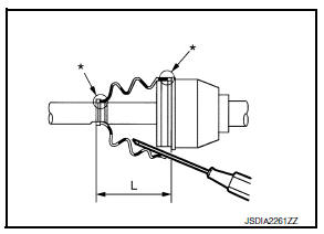
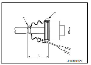
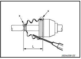
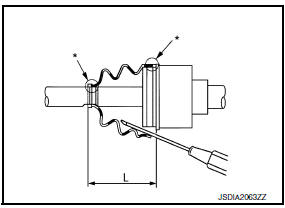
- Install the boot securely into the grooves (indicated by “*” marks) as shown.
CAUTION:
If there is grease on the boot mounting surfaces (indicated by “*” marks) on the shaft or the joint sub-assembly, the boot may come off. Remove all grease from the boot mounting surfaces.
- To prevent the deformation of the boot, adjust the boot installation length to the specified value by inserting a suitable tool into the inside of the boot from the large diameter side of the boot and discharging the inside air.
Boot installation length (L) : Refer to FAX-49, "Drive Shaft".
CAUTION:
- The boot may break if the boot installation length is not correct.
- Be careful not to touch the inside of the boot with the tip of the suitable tool.
- Install new large and small boot bands securely using Tool (A).
CAUTION:
Do not reuse the boot bands.
Tool number (A): KV40107300 ( – )
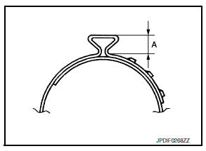
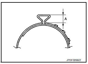
- Secure the boot band so that dimension (A) meets the specification.
Dimension (A) : Refer to FAX-49, "Drive Shaft".
- Attempt to rotate the boot to check whether or not the boot bands are securing the boot. If the boot is not secure, remove the boot bands, reposition the boot, and install new boot bands.
ASSEMBLY (TRANSAXLE SIDE)
- Install the dynamic damper using the following procedure:
- Install the dynamic damper to the shaft.
- Secure the dynamic damper in the correct position with new damper bands.
CAUTION:
Do not reuse the damper bands.
Dimension (A) : Refer to FAX-49, "Drive Shaft".
- Install the inner boot and the boot bands to the shaft.
CAUTION:
- Wrap the serration on the shaft with tape (A) to protect the boot from damage.
- Do not reuse the boot.
- Do not reuse the boot bands.
- Remove the tape wrapped around the serration on the shaft.
- Align the matching mark (A) on the spider assembly (1) with the matching mark on the shaft (2). Install the spider assembly to the shaft with the chamfer (B) facing the shaft.
- Secure the spider assembly onto the shaft with the snap ring (1).
CAUTION:
Do not reuse the snap ring.
- Apply the appropriate amount of grease (Genuine NISSAN Grease or equivalent) to the spider assembly and to the sliding surface.
NOTE:
Always check with the Parts Department for the latest parts information.
- Install the slide joint housing onto the spider assembly and pack the balance of the specified amount grease (Genuine NISSAN Grease or equivalent) into the slide joint housing.
Grease amount : Refer to FAX-49, "Drive Shaft".
- Align the matching marks on the slide joint housing and on the shaft.
- Install the boot securely into the grooves (indicated by “*” marks) as shown.
CAUTION:
If there is grease on the boot mounting surfaces (indicated by “*” marks) on the shaft or the joint sub-assembly, the boot may come off. Remove all grease from the boot mounting surfaces.
- To prevent the deformation of the boot, adjust the boot installation length to the specified value by inserting a suitable tool into the inside of the boot from the large diameter side of the boot and discharging the inside air.
Boot installation length (L) : Refer to FAX-49, "Drive Shaft".
CAUTION:
- The boot may break if the boot installation length is not correct.
- Be careful not to touch the inside of the boot with the tip of the suitable tool.
- Install the boot bands securely.
CAUTION:
Do not reuse the boot bands.
- Put boot band in the groove on drive shaft boot. Then fit pawls into holes to temporary installation.
NOTE:
For the large diameter side, fit projection (A) and guide slit (B) at first.
- Pinch projection on the band with suitable pliers to tighten band.
- Insert the tip of band into the lower part of pawl (marked with dotted circle) as shown.
- Attempt to rotate the boot to check whether or not the boot bands are securing the boot. If the boot is not secure, remove the boot bands, reposition the boot, and install new boot bands.
- Install the dust shield to the slide joint housing.
CAUTION:
Do not reuse the dust shield.
- Install the circular clip to the slide joint housing.
CAUTION:
Do not reuse the circular clip.
6M/T : Exploded View (RH)
- Joint sub-assembly
- Circular clip
- Boot band
- Boot
- Shaft
- Damper band
- Dynamic damper
- Boot band
- Boot
- Spider assembly
- Snap ring
- Slide joint housing
- Dust shield
- Support bearing
- Snap ring
- Dust shield
 Wheel side
6M/T : Disassembly and Assembly (RH)
DISASSEMBLY (WHEEL SIDE)
- Mount the drive shaft in a vise.
CAUTION:
When mounting the drive shaft in a vise, always use aluminum or copper plates between the vise and the drive shaft.
- Remove the boot bands and slide the boot back.
- Screw a suitable tool (A) into the joint sub-assembly screw part to a length of 30 mm (1.18 in) or more. Support the drive shaft with one hand and pull out the joint sub-assembly from the shaft
CAUTION:
- Align the suitable tool and the drive shaft. Remove the joint sub-assembly by pulling firmly and uniformly.
- If the joint sub-assembly cannot be removed after five or more attempts, replace the shaft and the joint sub-assembly as a set.
- Remove the circular clip from the shaft.
- Remove the outer boot from the shaft.
- Inspect the components. Refer to FAX-24, "6M/T : Inspection".
DISASSEMBLY (TRANSAXLE SIDE)
- Mount the drive shaft in a vise.
CAUTION:
When mounting the drive shaft in a vise, always use aluminum or copper plates between the vise and the drive shaft.
- Remove the boot bands and slide the boot back.
- Put matching marks on the slide joint housing and on the shaft.
CAUTION:
Use paint or an equivalent for matching marks. Do not scratch the surfaces.
- Remove the slide joint housing from the shaft.
- Put matching marks (A) on the spider assembly and on the shaft.
CAUTION:
Use paint or an equivalent for matching marks. Do not scratch the surfaces.
- Remove the snap ring (1).
- Remove the spider assembly from the shaft.
- Remove the inner boot from the shaft.
- Remove the damper bands.
- Remove the dynamic damper from the shaft.
- Remove the support bearing using the following procedure:
- Remove the dust shields from the slide joint housing.
- Remove the snap ring (1).
- Press out the support bearing from the slide joint housing.
- Remove the dust shield from the slide joint housing.
- Clean the old grease from the slide joint housing with paper waste.
- Inspect the components. Refer to FAX-24, "6M/T : Inspection".
ASSEMBLY (WHEEL SIDE)
- Clean the old grease from the joint sub-assembly using paper waste.
- Fill the serration slot on the joint sub-assembly (1) with NISSAN genuine grease or equivalent until the serration slot and ball groove become full to the brim.
CAUTION:
After applying the grease, use paper waste to wipe off the grease that has oozed out.
NOTE:
Always check with the Parts Department for the latest parts information.
- Install the outer boot and the boot bands to the shaft.
CAUTION:
- Wrap the serration on the shaft with tape (A) to protect the boot from damage.
- Do not reuse the boot.
- Do not reuse the boot bands.
- Remove the tape wrapped around the serration on the shaft.
- Position the circular clip (1) on the groove at the shaft edge.
CAUTION:
Do not reuse the circular clip.
NOTE:
A drive joint inserter is recommended when installing the circular clip.
- Align both center axles with the shaft edge and the joint subassembly.
Assemble the shaft with the joint sub-assembly while holding the circular clip.
- Install the joint sub-assembly to the shaft using a suitable tool.
CAUTION:
- Make sure the circular clip is properly positioned on the groove of the joint sub-assembly.
- Confirm that the joint sub-assembly is correctly engaged while rotating the drive shaft.
- Apply the specified amount of grease to the inside of the large diameter side of the boot.
NOTE:
Always check with the Parts Department for the latest parts information.
Grease amount : Refer to FAX-49, "Drive Shaft".
- Install the boot securely into the grooves (indicated by “*” marks) as shown.
CAUTION:
If there is grease on the boot mounting surfaces (indicated by “*” marks) on the shaft or the joint sub-assembly, the boot may come off. Remove all grease from the boot mounting surfaces.
- To prevent the deformation of the boot, adjust the boot installation length to the specified value by inserting a suitable tool into the inside of the boot from the large diameter side of the boot and discharging the inside air.
Boot installation length (L) : Refer to FAX-49, "Drive Shaft".
CAUTION:
- The boot may break if the boot installation length is not correct.
- Be careful not to touch the inside of the boot with the tip of the suitable tool.
- Install new large and small boot bands securely using Tool (A).
CAUTION:
Do not reuse the boot bands.
Tool number (A): KV40107300 ( – )
- Secure the boot band so that dimension (A) meets the specification.
Dimension (A) : Refer to FAX-49, "Drive Shaft".
- Attempt to rotate the boot to check whether or not the boot bands are securing the boot. If the boot is not secure, remove the boot bands, reposition the boot, and install new boot bands.
ASSEMBLY (TRANSAXLE SIDE)
- Install the support bearing using the following procedure:
- Install the dust shield to the slide joint housing.
CAUTION:
Do not reuse the dust shield.
- Press the support bearing (1) onto the slide joint housing using the suitable tool (A).
CAUTION:
Do not reuse the support bearing.
- Install the snap ring (1).
CAUTION:
Do not reuse the snap ring.
- Install the dust shields.
CAUTION:
Do not reuse the dust shield.
- Install the dynamic damper using the following procedure:
- Install the dynamic damper to the shaft.
- Secure the dynamic damper in the correct position with new damper bands.
CAUTION:
Do not reuse the damper bands.
Dimension (A) : Refer to FAX-49, "Drive Shaft".
- Install the inner boot and the boot bands to the shaft.
CAUTION:
- Wrap the serration on the shaft with tape (A) to protect the boot from damage.
- Do not reuse the boot.
- Do not reuse the boot bands.
- Remove the tape wrapped around the serration on the shaft.
- Align the matching mark (A) on the spider assembly (1) with the matching mark on the shaft (2). Install the spider assembly to the shaft with the chamfer (B) facing the shaft.
- Secure the spider assembly onto the shaft with the snap ring (1).
CAUTION:
Do not reuse the snap ring.
- Apply the appropriate amount of grease (Genuine NISSAN Grease or equivalent) to the spider assembly and to the sliding surface.
NOTE:
Always check with the Parts Department for the latest parts information.
- Install the slide joint housing onto the spider assembly and pack the balance of the specified amount grease (Genuine NISSAN Grease or equivalent) into the slide joint housing.
Grease amount : Refer to FAX-49, "Drive Shaft".
- Align the matching marks on the slide joint housing and on the shaft.
- Install the boot securely into the grooves (indicated by “*” marks) as shown.
CAUTION:
If there is grease on the boot mounting surfaces (indicated by “*” marks) on the shaft or the joint sub-assembly, the boot may come off. Remove all grease from the boot mounting surfaces.
- To prevent the deformation of the boot, adjust the boot installation length to the specified value by inserting a suitable tool into the inside of the boot from the large diameter side of the boot and discharging the inside air.
Boot installation length (L) : Refer to FAX-49, "Drive Shaft".
CAUTION:
- The boot may break if the boot installation length is not correct.
- Be careful not to touch the inside of the boot with the tip of the suitable tool.
- Install the boot bands securely
CAUTION:
Do not reuse the boot bands.
- Put boot band in the groove on drive shaft boot. Then fit pawls into holes to temporary installation
NOTE:
For the large diameter side, fit projection (A) and guide slit (B) at first.
- Pinch projection on the band with suitable pliers to tighten band.

- Insert the tip of band into the lower part of pawl (marked with dotted circle) as shown.
- Attempt to rotate the boot to check whether or not the boot bands are securing the boot. If the boot is not secure, remove the boot bands, reposition the boot, and install new boot bands.
 Unit disassembly and assembly
Front drive shaft ...
 Except 6M/T
EXCEPT 6M/T : Exploded View
Circular clip
Dust shield
Slide joint housing
Snap ring
Spider assembly
Boot band
Boot
Shaft
Damper band
Dynamic damper
Circular clip
Joint s ...
Other materials:
Precaution for Work
When removing or disassembling each component, be careful not to damage
or deform it. If a component
may be subject to interference, be sure to protect it with a shop cloth.
When removing (disengaging) components with a screwdriver or similar
tool, be sure to wrap the component
with a ...
Symptom diagnosis
Push-button ignition switch does not operate
Description
Check that vehicle is under the condition shown in “Conditions of vehicle”
before starting diagnosis, and check
each symptom.
Note:
The engine start function, door lock function, power distribution system,
and nats-ivis/nvis ...
Push-button ignition switch illumination circuit
Description
Provides the power supply and the ground to control the push-button ignition
switch illumination.
Component function check
1.Check push-button ignition switch illumination operation
Consult active test
Turn the ignition switch ON.
Select engine sw illumi of bcm (intelligen ...
