Nissan Sentra Service Manual: VDC OFF Switch
Component Function Check
1.CHECK VDC OFF SWITCH OPERATION
Check that VDC OFF indicator lamp in combination meter turns ON/OFF when VDC OFF switch is operated.
Is the inspection result normal? YES >> Inspection End.
NO >> Proceed to diagnosis procedure. Refer to BRC-92, "Diagnosis Procedure".
Diagnosis Procedure
Regarding Wiring Diagram information, refer to BRC-44, "Wiring Diagram".
1.CONNECTOR INSPECTION
-
Turn ignition switch OFF.
-
Disconnect ABS actuator and electric unit (control unit) and VDC OFF switch connectors.
-
Check connectors and terminals for deformation, disconnection, looseness or damage.
Is the inspection result normal? YES >> GO TO 2.
NO >> Repair or replace as necessary.
2.CHECK VDC OFF SWITCH
Check VDC OFF switch. Refer to BRC-93, "Component Inspection".
Is the inspection result normal? YES >> GO TO 3.
NO >> Replace VDC OFF switch. Refer to BRC-112, "Removal and Installation".
3.Check VDC OFF Switch signal
 With CONSULT.
-
Connect ABS actuator and electric unit (control unit) and VDC OFF switch connectors.
-
Turn ignition switch ON.
-
In “DATA MONITOR” select “OFF SW” and check VDC OFF switch signal.
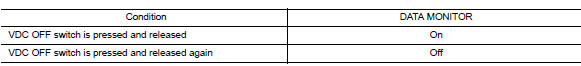
Is the inspection result normal? YES >> Refer to BRC-51, "Work Flow".
NO >> GO TO 4.
4.Check VDC OFF Switch circuit
-
Turn ignition switch OFF.
-
Disconnect ABS actuator and electric unit (control unit) and VDC OFF switch connectors.
-
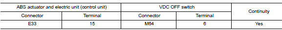
Check continuity between ABS actuator and electric unit (control unit) connector E33 terminal 15 and VDC OFF switch connector M64 terminal 6.
-
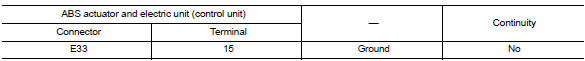
Check continuity between ABS actuator and electric unit (control unit) connector terminal E33 terminal 15 and ground.
Is the inspection result normal? YES >> GO TO 5.
NO >> Repair or replace malfunctioning components.
5.Check vdc off switch ground circuit
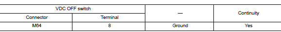
Check continuity between VDC OFF switch connector M64 terminal 8 and ground.
Is the inspection result normal? YES >> Replace ABS actuator and electric unit (control unit). Refer to BRC-110, "Removal and Installation".
NO >> Repair or replace malfunctioning components.
Component Inspection
1.Check vdc off switch
-
Turn ignition switch OFF.
-
Disconnect VDC OFF switch connector.
-
Check continuity between terminals of VDC OFF switch connector.
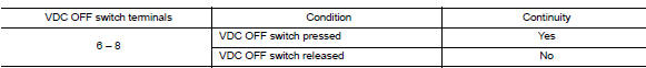
Is the inspection result normal? YES >> Inspection End.
NO >> Replace VDC OFF switch. Refer to BRC-112, "Removal and Installation".
 Parking brake switch
Component Function Check
1.CHECK PARKING BRAKE SWITCH OPERATION
Check that brake warning lamp in combination meter turns ON/OFF
when parking brake is actuated.
Is the inspection result normal?
...
 ABS Warning lamp
Component Function Check
1.CHECK ABS WARNING LAMP FUNCTION
Check that ABS warning lamp in combination meter turns ON for
approximately 2 seconds after ignition switch
is turned ON.
Is the ins ...
Other materials:
Shift lock system
Component Function Check
1.CHECK SHIFT LOCK OPERATION (PART 1)
Turn ignition switch ON.
Shift the selector lever to park “P” position.
Attempt to shift the selector lever to any other position with the brake
pedal released.
Can the selector lever be shifted to any other posi ...
Roof side molding
Exploded view
Roof side molding
Roof side molding clip
Roof panel
Body side outer panel
Adhesive tape
Removal and installation
REMOVAL
ROOF SIDE MOLDING
Release roof side molding rear side clip, using a suitable tool
(A).
Clip
Front
CAUTION:
Apply protective tape ...
Dtc/circuit diagnosis
U1000 can comm circuit
Description
Refer to LAN-7, "CAN COMMUNICATION SYSTEM : System Description".
Dtc logic
DTC DETECTION LOGIC
NOTE:
U1000 can be set if a module harness was disconnected and reconnected,
perhaps during a repair. Confirm
that there are actual CAN diagnostic sym ...
