Nissan Sentra Service Manual: Vacuum lines
Exploded View
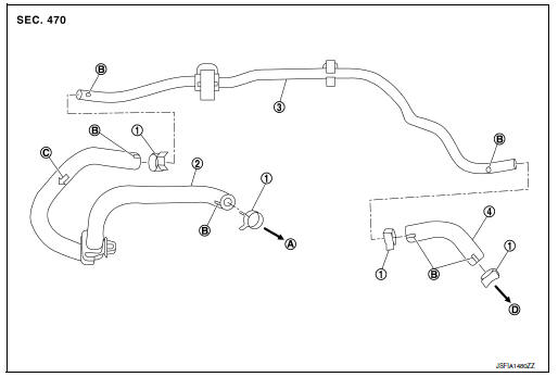
- Clamp
- Vacuum hose (built-in check valve)
- Vacuum piping
- Vacuum hose
- To intake manifold side
- Paint mark
- Stamp indicating engine direction
- To brake booster
Removal and Installation
REMOVAL
- Remove air duct and air cleaner case. Refer to EM-25, "Removal and Installation".
- Remove the vacuum hoses and vacuum piping.
INSPECTION AFTER REMOVAL
Visual Inspection
Check for correct installation, damage and deterioration of the vacuum hoses and pipe.
Valve Air-tightness Check
- Connect a suitable tool at each end of the vacuum hose with built-in check valve to inspect the check valve operation.
Vacuum applied at booster end : Refer to BR-54, "Check Valve".
Vacuum applied at intake manifold end : Refer to BR-54, "Check Valve".
- Replace the vacuum hose with built-in check valve if out of specification.
INSTALLATION
Installation is in the reverse order of removal.
- When installing vacuum hose, insert it until its tip reaches the back-end of length (A) or further as shown.
CAUTION:
Do not use lubricating oil during assembly
Length (A) : 24 mm (0.95 in) or more
- Face the paint mark of vacuum hose (build-in check valve) (intake manifold side) to vehicle right side to assemble.
- Face the paint mark of vacuum hose (build-in check valve) (brake booster side) to vehicle front side to assemble.
- Face the paint mark of vacuum piping (intake manifold side) to vehicle front side to assemble.
- Face the paint mark of vacuum piping (brake booster side) to downward to assemble.
- Face the paint mark of vacuum hose (intake manifold side) to downward to assemble.
- Face the paint mark of vacuum hose (brake booster side) to vehicle front side to assemble.
- For clamp mounting direction (the orientation of pawl), refer to BR-36, "Exploded View".
 Brake booster
Exploded View
Master cylinder assembly
Brake booster
Lock nut
Clevis
Gasket
Spacer
Removal and installation
REMOVAL
Remove cowl top and cowl top extension. Refer to EXT-26, ...
 Front disc brake
BRAKE PAD
BRAKE PAD : Exploded View
Cylinder body
Inner shim cover
Inner shim
Inner pad (with pad wear sensor)
Pad retainer
Torque member
Outer pad
Outer shim
Outer shim cover ...
Other materials:
EPS warning lamp does not turn OFF
Description
EPS warning lamp does not turn OFF several seconds after engine
started.
Diagnosis Procedure
1.PERFORM SELF-DIAGNOSIS
With CONSULT
Turn the ignition switch OFF to ON.
Perform “EPS” self-diagnosis.
Is any DTC detected?
YES >> Check the DTC. Refer to ...
Power supply and ground circuit
A/C AUTO AMP
A/C AUTO AMP. : Diagnosis Procedure
Regarding Wiring Diagram information, refer to HAC-41, "Wiring Diagram".
1.CHECK FUSE
Check fuses [No. 5, 8 and 21, located in the fuse block (J/B)].
NOTE:
Refer to PG-47, "Terminal Arrangement".
Is the inspection result nor ...
Malfunction indicator lamp
Component Function Check
1.CHECK MIL FUNCTION
Turn ignition switch ON.
Check that MIL lights up.
Is the inspection result normal?
YES >> INSPECTION END
NO >> Proceed to EC-467, "Diagnosis Procedure".
Diagnosis Procedure
1.CHECK DTC WITH ECM
Check that DTC UXXXX i ...
