Nissan Sentra Service Manual: Unit removal and installation
Front suspension member
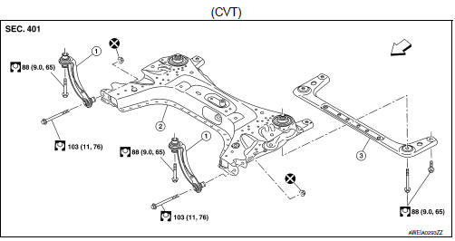
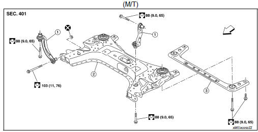
Exploded View
- Upper link
- Front suspension member
- Member stay
 Front
Front
- Upper link
- Front suspension member
- Member stay
 Front
Front
Removal and Installation
REMOVAL
- Remove the front wheel and tire using power tool. Refer to WT-47, "Exploded View".
- Remove the front under cover and the engine under cover. Refer to EXT-30, "FRONT UNDER COVER : Removal and Installation".
- Disconnect the steering gear from the lower shaft. Refer to ST-12, "Removal and Installation".
- Disconnect the steering outer socket from the steering knuckle. Refer to ST-14, "Removal and Installation".
- Remove the nut and bolt from the lower ball joint. Disconnect the transverse link from the steering knuckle. Refer to FAX-8, "Exploded View".
- Remove the rear torque rod and the rear torque rod bracket.
- MRA8DE (M/T): Refer to EM-82, "M/T : Removal and Installation".
- MRA8DE (CVT): Refer to EM-86, "CVT : Removal and Installation".
- Disconnect the oxygen sensor. Refer to EX-5, "Removal and Installation".
- Disconnect the stabilizer connecting rod from the stabilizer bar. Refer to FSU-12, "Exploded View".
- Set a suitable jack under front suspension member.
CAUTION:
- At this step, the suitable jack must be set only for supporting the removal procedure. For details on jacking up the vehicle, refer to GI-31, "Garage Jack and Safety Stand and 2-Pole Lift".
- Do not damage the front suspension member with the suitable jack.
- Remove the lower bolts from the upper links.
- Remove the bolts and the member stay.
- Remove the front suspension member bolts.
- Gradually lower the suitable jack to remove the front suspension member from the vehicle.
CAUTION:
Make sure the front suspension member is stable when using the suitable jack.
- If replacing the front suspension member, perform the following procedures:
- Remove the steering gear. Refer to ST-14, "Exploded View".
- Remove the transverse links. Refer to FSU-10, "Exploded View".
- Remove the stabilizer bar, the stabilizer clamps, and the stabilizer bushings. Refer to FSU-12, "Exploded View".
- Remove the oxygen sensor bracket. Refer to EX-5, "Exploded View".
- Inspect the components. Refer to FSU-18, "Inspection".
INSTALLATION
Installation is in the reverse order of removal.
CAUTION:
Do not reuse the transverse link nuts.
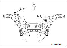
- Install the member stay bolts, the upper link bolts, and the front suspension member bolts in the order of 1 to 10 as shown (if equipped with the 6M/T).
Temporary tightening : 1 → 2→ 3 → 4
Final tightening (Specified torque) : 5 → 6 → 7 → 8 → 9 → 10
 : Front
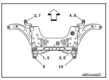
- Install the member stay bolts, the upper link bolts, and the front suspension member bolts in the order of 1 to 10 as shown (if equipped with the CVT).
Temporary tightening : 1 → 2→ 3 → 4
Final tightening (Specified torque) : 5 → 6 → 7 → 8 → 9 → 10
 : Front
- Perform the final tightening of the nuts and bolts under unladen conditions with the tires on level ground.
- Complete the inspection. Refer to FSU-18, "Inspection".
Inspection
INSPECTION AFTER REMOVAL
Check the front suspension member for cracks, wear or damage. Replace components if necessary.
INSPECTION AFTER INSTALLATION
- Check the wheel sensor harness to be sure the connectors are fully seated.
- Check the neutral position of the steering angle sensor. Refer to BRC-54, "Work Procedure".
- Check the wheel alignment. Refer to FSU-6, "Inspection".
 Steering knuckle
Exploded View
Steering knuckle
Splash guard
Wheel stud
Wheel hub and bearing
Disc brake rotor
Wheel hub lock nut
Nut retainer
Cotter pin
Removal and Installation
REMOVAL
...
 Unit disassembly and assembly
Front coil spring and strut
Exploded View
Piston rod lock nut
Strut mount insulator
Strut mount bearing
Bound bumper
Coil spring
Lower rubber seat
Strut
Steering knuckle
Fro ...
Other materials:
Description
Number
Item
Description
1
Power supply
This means the power supply of fusible link or fuse.
2
Fusible link
“X” means the fusible link.
3
Number of fusible link/
fuse
This means the numbe ...
Child safety rear door lock
Child safety locks help prevent the rear doors
from being opened accidentally, especially when
small children are in the vehicle.
The child safety lock levers are located on the
edge of the rear doors.
When the lever is in the unlock position 2 , the
door can be opened from the outside ...
Removal and installation
Ecm
Exploded View
ECM bracket
ECM
Engine mounting insulator bracket
Removal and Installation
CAUTION:
Perform ADDITIONAL SERVICE WHEN REPLACING ECM. Refer to EC-135, "Work
Procedure".
REMOVAL
Remove battery. Refer to PG-50, "Removal and Installation (Battery)& ...
