Nissan Sentra Service Manual: Unit disassembly and assembly
Steering gear and linkage
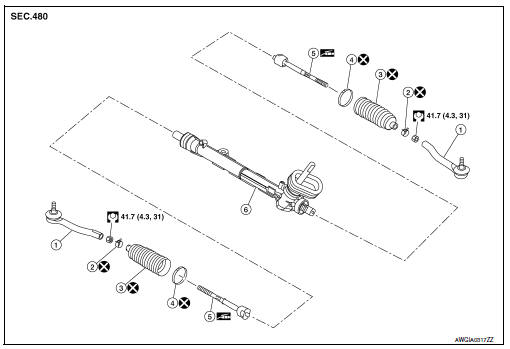
Exploded View
-
Outer socket
-
Boot clamp (small diameter)
-
Boot
-
Boot clamp (large diameter)
-
Inner socket
-
Gear housing assembly
Disassembly and Assembly
DISASSEMBLY
-
Loosen outer socket lock nut, and remove outer socket.
CAUTION:
When loosening lock nut, be sure to fix outer socket with a wrench or an equivalent.
-
Remove boot clamps, and then remove boot from inner socket.
CAUTION:
-
Do not damage inner socket part and gear housing part of steering gear assembly when removing boot. steering gear assembly must be replaced if steering gear assembly are damaged because it may cause foreign material interfusion.
-
Do not reuse boot clamps.
-
Remove inner socket.
ASSEMBLY
-
Apply recommended grease to inner socket (A) of gear housing assembly, and install boot to gear housing assembly.
Use Genuine Lithium Soap, Autorex A (manufactured by Kyodo yushi) or equivalent.
CAUTION:
Do not reuse boot.
Grease application position (Reference) (B) : 10 mm (0.39 in)
-
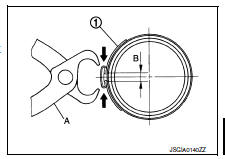
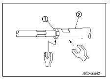
Install boot clamp (large diameter) (1) to boot using Tool.
CAUTION:
-
Do not reuse boot clamp (large diameter).
-
Install boot clamp (large diameter) securely to boot groove, and crimp it so as to have clearance (B) of 3 mm (0.12 in) or less as shown.
Tool number (A) : KV40107300 ( — )
-
Install boot clamp (small diameter) to boot.
CAUTION:
Do not reuse boot clamp (small diameter).
-
Adjust inner socket to standard length (L), and then tighten outer socket lock nut (1) to the specified torque. Check length again after tightening lock nut.
(L) : Refer to ST-19, "Power Steering Gear".
CAUTION:
-
When tightening the outer socket lock nut (1), be sure to fix outer socket (2) with suitable tool to prevent the ball joint from getting contact with the knuckle.
-
Adjust toe-in after this procedure. The length achieved after toe-in adjustment is not necessary the above value.
 Steering gear and linkage
Exploded View
REMOVAL
Steering gear assembly
Front suspension member
Front
Removal and Installation
REMOVAL
Set steering wheel to the straight-ahead position.
Remove ...
 Service data and specifications (SDS)
Steering Wheel
Steering Angle
Steering Column
STEERING COLUMN LENGTH
TILT MECHANISM OPERATING RANGE
Power Steering Gear
STEERING OUTER SOCKET AND INNER SOCKET
RACK STROKE
...
Other materials:
Locking with key
Driver’s side
The power door lock system allows you to lock or
unlock all doors at the same time.
Turning the key toward the front 1 of the vehicle
locks all doors.
Turning the key one time toward the rear 2 of the
vehicle unlocks that door. From that position,
returning the key to ...
Power windows do not operate with power window main switch
Diagnosis Procedure
1.Check bcm power supply and ground circuit
Check bcm power supply and ground circuit.
Refer to bcs-67, "diagnosis procedure" (with intelligent key) or bcs-120,
"diagnosis procedure" (without
intelligent key).
Is the inspection result normal?
Yes & ...
Precaution for Work
When removing or disassembling each component, be careful not to damage
or deform it. If a component
may be subject to interference, be sure to protect it with a shop cloth.
When removing (disengaging) components with a screwdriver or similar
tool, be sure to wrap the component
with a ...
