Nissan Sentra Service Manual: Trunk room lamp circuit
Description
Controls the trunk room lamp (ground side) to turn the trunk room lamp on and off.
Diagnosis Procedure
Regarding wiring diagram information, refer to inl-17, "wiring diagram".
Caution:
Before performing the diagnosis, check that the following are normal.
- Interior room lamp power supply
- Trunk room lamp bulb
1.Check trunk room lamp output
- Turn ignition switch OFF.
- Remove the trunk room lamp bulb.
- Check continuity between bcm harness connector and ground.
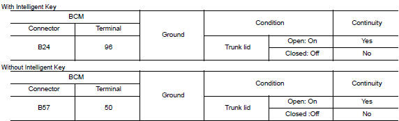
Is the inspection result normal? Yes >> trunk room lamp control circuit is operating normally.
Fixed on>>go to 3.
Fixed off>>go to 2.
2.Check trunk room lamp open circuit
Check continuity between bcm harness connector and trunk room lamp harness connector.
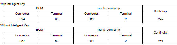
Is the inspection result normal? Yes >> check trunk room lamp for an open. If ng, replace lamp. Refer to inl-56, "removal and installation".
If ok, replace bcm. Refer to bcs-73, "removal and installation" (with intelligent key), bcs-126, "removal and installation" (without intelligent key).
No >> repair or replace harness or connector.
3.Check trunk room lamp short to ground
- Disconnect bcm harness connector.
- Check continuity between BCM harness connector and ground.
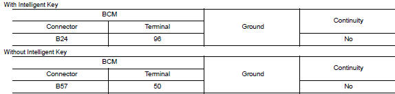
Is the inspection result normal? Yes >> check trunk room lamp for an internal short to ground. If ng, replace lamp. Refer to inl-56, "removal and installation". If ok, replace bcm. Refer to bcs-73, "removal and installation" (with intelligent key), bcs-126, "removal and installation" (without intelligent key).
No >> repair or replace harness or connector.
 Interior room lamp control circuit
Description
Controls each interior room lamp (ground side) by pwm signal.
Note:
Pwm signal control period is approximately 250 hz (in the gradual
brightening/dimming).
Component function check
...
 Push-button ignition switch illumination circuit
Description
Provides the power supply and the ground to control the push-button ignition
switch illumination.
Component function check
1.Check push-button ignition switch illumination operation ...
Other materials:
P2118 Throttle control motor
DTC Logic
DTC DETECTION LOGIC
DTC No.
CONSULT screen terms
(Trouble diagnosis content)
DTC detecting condition
Possible cause
P2118
ETC MOT-B1
(Throttle actuator control
motor current range/
performance)
ECM detects short in both circuits between
ECM a ...
System description
Component parts
Body control system
Body control system : component parts location
BCM (view with instrument panel removed)
Combination switch reading system
Combination switch reading system : component parts location
BCM (view with combination meter
removed)
Combination s ...
BluetoothÂź streaming audio without Navigation System (if so equipped)
If you have a compatible BluetoothÂź audio device
that is capable of playing audio files, the
device can be connected to the vehicleâs audio
system so that the audio files on the device play
through the vehicleâs speakers.
Connecting BluetoothÂź audio
To connect your BluetoothÂź audio devi ...
