Nissan Sentra Service Manual: Transmitter
Exploded View
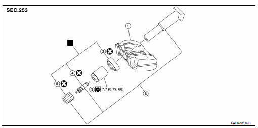
- Transmitter (tire pressure sensor)
- O-ring
- Valve stem nut
- Valve core
- Valve cap
- Valve stem assembly
 Parts that are replaced as a set
when the tire is replaced.
Removal and Installation
REMOVAL
- Remove road wheel and tire assembly using power tool.
- Remove valve cap and valve core to deflate the tire.
NOTE:
If the tire is to be reused, apply a matching mark on the tire in line with the position of the road wheel valve stem assembly for the purpose of road wheel and tire balance adjustment after installation.
- Remove the valve stem nut and allow transmitter to fall into tire.
- Lubricate the tire outside bead well with a suitable non-silicone lubricant, and remove outside of tire from the road wheel. Reach inside the tire and remove the transmitter.
CAUTION:
- Do not use silicone lubricant. Use of silicone lubricant will deteriorate the tire and road wheel.
- Be sure not to damage the road wheel or transmitter.
- Do not allow lubricant to make contact with transmitter.
- Lubricate the tire inside bead well with a suitable non-silicone lubricant, and remove inside of tire from the road wheel.
CAUTION:
- Do not use silicone lubricant. Use of silicone lubricant will deteriorate the tire and road wheel.
- Be sure not to damage the road wheel.
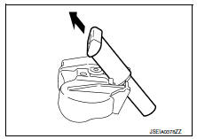
- Remove the valve stem from the transmitter as shown.
INSTALLATION
- Apply a suitable non-silicone lubricant to the tire inside bead.
CAUTION:
Do not use silicone lubricant. Use of silicone lubricant will deteriorate the tire and road wheel.
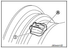
- Install the tire inside bead (1) onto the road wheel (2) in the position shown.
INSTALLATION
- Apply a suitable non-silicone lubricant to the tire inside bead.
CAUTION:
Do not use silicone lubricant. Use of silicone lubricant will deteriorate the tire and road wheel.
- Install the tire inside bead (1) onto the road wheel (2) in the position shown.
- Install the valve stem to the transmitter
- Install the O-ring to the transmitter.
CAUTION:
- Do not reuse O-ring
- Insert O-ring to the base of the transmitter.
- The base of the valve stem (A) must be positioned in the groove of the metal plate as shown.
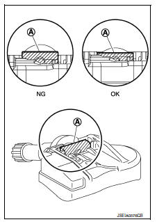
- Install transmitter (1) to road wheel while pressing at position (A).
CAUTION:
- Check that O-ring contacts horizontally with road wheel.
- Check that the base of the valve stem is positioned in the groove of the metal plate.
- Install and tighten the valve stem nut to the specified torque.
Valve stem nut tightening torque Refer to WT-50, "Exploded View".
CAUTION:
Do not use power tool for installation.
- Place road wheel on turntable of tire machine. Ensure that transmitter is 270 degrees from mounting/dismounting head.
NOTE:
Do not touch transmitter with mounting head.
- Apply a suitable non-silicone lubricant to the tire outside bead.
CAUTION:
- Do not use silicone lubricant. Use of silicone lubricant will deteriorate the tire and road wheel.
- Do not allow lubricant to make contact with transmitter.
- Install the tire outside bead onto the road wheel as normal.
NOTE:
If the tire is being reused, align the matching mark applied on the tire with the position of the road wheel valve stem assembly for the purpose of road wheel and tire balance adjustment after installation. Ensure that the tire does not rotate relative to road wheel.
- Install the valve core and inflate tire.
CAUTION:
Do not reuse valve core.
- Install the valve cap.
CAUTION:
Do not reuse valve cap.
- Balance the road wheel and tire assembly. Refer to WT-47, "Adjustment".
- Install road wheel and tire assembly in appropriate wheel position on vehicle. Refer to WT-47, "Removal and Installation".
NOTE:
If replacing the transmitter, then transmitter wake up operation must be performed. Refer to WT-22, "Work Procedure".
- Adjust neutral position of steering angle sensor. Refer to BRC-54, "Work Procedure".
Tire pressure receiver
Removal and Installation
The tire pressure receiver is integral to the remote keyless entry receiver. Refer to DLK-199, "Removal and Installation".
 Road wheel tire assembly
Exploded View
Removal and Installation
REMOVAL
Remove wheel nuts.
Remove wheel and tire.
INSTALLATION
Installation is in the reverse order of removal.
Adjustment
BALANCING WHEELS (A ...
 Service data and specifications (SDS)
Road Wheel
Tire Air Pressure
M/T - CVT MODELS
CVT MODELS
...
Other materials:
P1651 Starter motor relay
Description
ECM controls ON/OFF state of the starter relay, according to the engine and
vehicle condition. ECM transmits
a control signal to IPDM E/R by CAN communication.
Under normal conditions, ECM controls and maintains the starter relay in OFF
state during following condition:
Engi ...
Unit disassembly and assembly
Front coil spring and strut
Exploded View
Piston rod lock nut
Strut mount insulator
Strut mount bearing
Bound bumper
Coil spring
Lower rubber seat
Strut
Steering knuckle
Front
Disassembly and Assembly
DISASSEMBLY
CAUTION:
Do not damage the piston rod when removing comp ...
Basic inspection
Diagnosis and repair work flow
Work flow
OVERALL SEQUENCE
Detailed flow
1.Get information for symptom
Get detailed information from the customer about the symptom (the
condition and the environment when
the incident/malfunction occurs)
Check operation condition of the function tha ...
