Nissan Sentra Service Manual: Timing chain
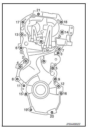
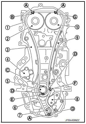
Exploded View
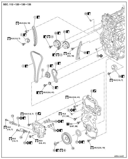
- Timing chain slack guide
- Timing chain tensioner
- Timing chain
- Oil pump drive chain
- Crankshaft sprocket
- Crankshaft key
- Oil pump sprocket
- Front cover
- O-ring
- O-ring
- Valve timing control solenoid valve cover
- O-ring
- Valve timing control solenoid valve (EXH)
- Valve timing control solenoid valve (INT)
- Crankshaft pulley bolt
- Crankshaft pulley
- Front oil seal
- Oil pump drive chain tensioner
- O-ring
- Timing chain tension guide
- Camshaft sprocket (INT)
- Camshaft sprocket (EXH)
- O-ring
- Refer to EM-60
- Refer to INSTALLATION
Removal and Installation
REMOVAL
CAUTION:
The rotating direction is shown from the engine front.
- Disconnect battery negative terminal. Refer to PG-50, "Exploded View".
- Drain engine oil. Refer to LU-8, "Draining".
CAUTION:
Perform this step when engine is cold.
- Remove intake manifold. Refer to EM-27, "Exploded View".
- Remove the rocker cover. Refer to EM-12, "Exploded View".
- Remove fender protector side cover (RH). Refer to EXT-27, "FENDER PROTECTOR : Exploded View".
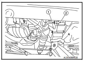
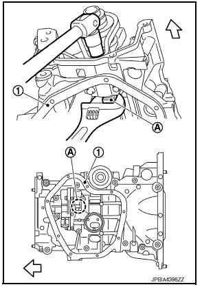
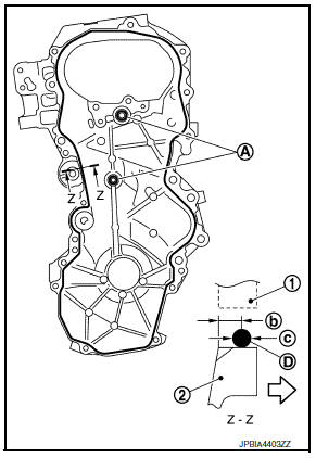
- Support engine (1) and transaxle (2) using suitable jack (A).
CAUTION:
- Position a suitable jack under the engine and transaxle assembly as shown.
- Do not damage the front exhaust tube or transaxle oil pan with the jack.
- Remove upper torque rod and engine mounting insulator (RH). Refer to EM-82, "M/T : Exploded View" (M/T) or EM-86, "CVT : Exploded View" (CVT).
- Set No. 1 cylinder at TDC on its compression stroke with the following procedure:
- Rotate crankshaft pulley (1) clockwise and align TDC mark (no paint) (B) to timing indicator (A) on front cover.
(C) : White paint mark (Not used for service)
- At the same time, check that the cam lobes of the No. 1 cylinder
are located (
 ) as shown.
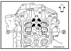
(1) : Camshaft (INT)
(2) : Camshaft (EXH)
- If not, rotate crankshaft pulley one revolution (360 degrees) and align as shown.
- Remove crankshaft pulley with the following procedure:
- Remove drive belt. Refer to EM-15, "Exploded View".
- Lock crankshaft pulley (1) using suitable tool (A), loosen crankshaft pulley bolt, and locate bolt seating surface at 10 mm (0.39 in) from its original position.
CAUTION:
Do not remove the crankshaft pulley bolt as it will be used as a supporting point for the Tool.
Tool number : KV11103000 ( — )
- Attach Tool (A) in the M6 thread hole on crankshaft pulley (1), and remove crankshaft pulley.
Tool number : KV11103000 ( — )
- Remove oil pan (lower). Refer to EM-33, "Exploded View".
NOTE:
If crankshaft sprocket and oil pump drive component are not removed, this step is unnecessary.
- Remove intake valve timing control solenoid valve.
- Remove drive belt auto-tensioner. Refer to EM-16, "Exploded View".
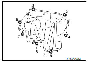
- Remove front cover with the following procedure:
- Loosen bolts in reverse order as shown.
- Cut liquid gasket by prying the position (
 ) shown using suitable
tool, and then remove the front cover.
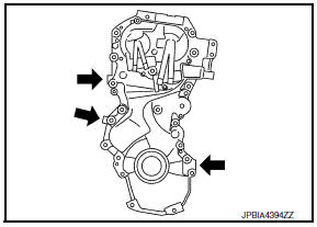
CAUTION:
- Be careful not to damage the mating surface.
- Do not use suitable tool anywhere other than shown, sealant used is more adhesive than previous types when shipped.
- Remove front oil seal from front cover.
CAUTION:
Be careful not to damage front cover.
- Pull out front oil seal using suitable tool.
- Remove valve timing control cover, if necessary.
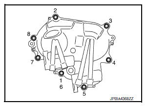
- Loosen bolts in reverse order as shown.
NOTE:
Disregard the numerical order No.1 in removal
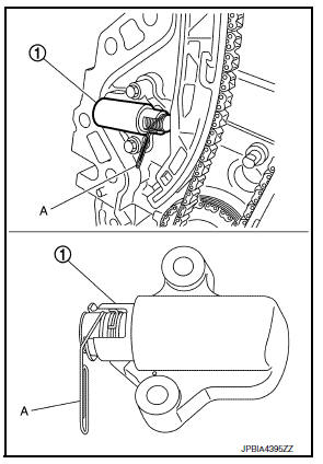
- Remove timing chain tensioner with the following procedure:
- Insert a stopper pin (A) into the top groove with the timing chain tensioner plunger pressed.
NOTE:
Timing chain tensioner plunger is securely locked by inserting a stopper pin.
- Remove timing chain tensioner (1).
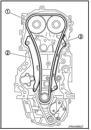
- Remove slack guide (2), tension guide (3) and timing chain (1).
CAUTION:
Do not rotate each crankshaft and camshaft individually while timing chain is removed. It causes interference between valve and piston.
NOTE:
If timing chain is difficult to remove, remove camshaft sprocket (EXH) first to remove timing chain.
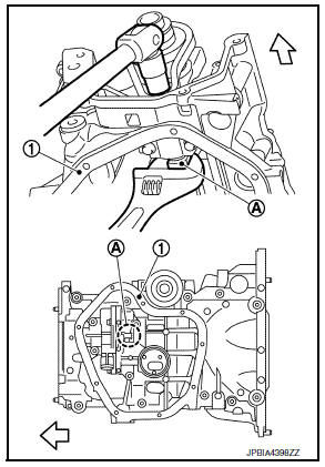
- Remove crankshaft sprocket and oil pump drive component with the following procedure:
- Push oil pump drive chain tensioner (1) in the direction as shown.
- Insert a stopper pin (A) into the body hole (B).
- Remove oil pump chain tensioner.
- When the holes on lever and tensioner body cannot be aligned, align these holes by slightly moving the oil pump chain tensioner slack guide.
- Hold the WAF part of oil pump shaft [WAF: 10 mm (0.39 in)] (A), and then loosen the oil pump sprocket bolt and remove it.
(1) : Oil pan (upper)
CAUTION:
- Secure the oil pump shaft with the WAF part.
- Do not loosen the oil pump sprocket bolt by tightening the oil pump drive chain.
INSTALLATION
CAUTION:
Do not reuse O-rings.
NOTE:
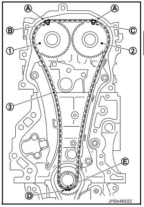
The figure shows the relationship between the matching mark on each timing chain and that on the corresponding sprocket, with the components installed.
(1) : Timing chain
(2) : Camshaft sprocket (EXH)
(3) : Slack guide
(4) : Timing chain tensioner
(5) : Crankshaft sprocket
(6) : Oil pump drive chain
(7) : Oil pump sprocket
(8) : Oil pump drive chain tensioner
(9) : Tension guide
(10) : Camshaft sprocket (INT)
(A) : Matching mark (dark blue link)
(B) : Matching mark (outer groove)
(C) : Crankshaft key position (straight up)
(D) : Matching mark (stamping)
(E) : Matching mark (white link)
(F) : Matching mark (yellow link)
(G) : Matching mark (outer groove)
- Check that crankshaft key points straight up.
- Install crankshaft sprocket (2), oil pump sprocket (3) and oil pump drive chain (1).
(A) : Matching mark (stamping)
(B) : Matching mark (yellow link)
(C) : Matching mark (dark blue link)
- Install it by aligning matching marks on each sprockets and oil pump drive chain.
- If these matching marks are not aligned, rotate the oil pump shaft slightly to correct the position.
CAUTION:
Check matching mark position of each sprocket after installing the oil pump drive chain.
- Hold the WAF part of oil pump shaft [WAF: 10 mm (0.39 in)] (A), and then tighten the oil pump shaft sprocket bolt.
(1) : Oil pan (upper)
CAUTION:
- Secure the oil pump shaft with the WAF part.
- Do not loosen the oil pump shaft sprocket bolt by tightening the oil pump drive chain.
- Install oil pump chain tensioner (1).
- Fix the face of the oil pump tensioner at the most compressed position using a stopper pin (A), and then install it.
- Securely pull out (
 ) the
) the
stopper pin after installing the oil pump chain tensioner. - Check matching mark position of oil pump drive chain and each sprocket again.
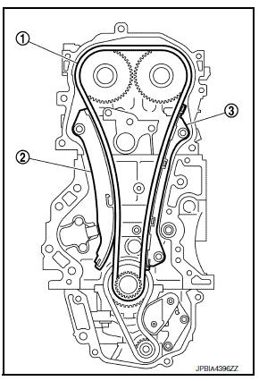
- Align the matching marks of each sprocket with the matching marks of timing chain.
(1) : Camshaft sprocket (EXH)
(2) : Camshaft sprocket (INT)
(3) : Timing chain
(A) : Matching mark (dark blue link)
(B) : Matching mark (outer groove)
(C) : Matching mark (outer groove)
(D) : Matching mark (copper link)
(E) : Matching mark (stamping)
- If these matching marks are not aligned, rotate the camshaft slightly by holding the hexagonal portion to correct the position.
CAUTION:
Check matching mark position of each sprocket and timing chain again after installing the timing chain.
- Install the slack guide (2) and the tension guide (3).
(1) : Timing chain
- Install timing chain tensioner.
- Lock the plunger at the most compressed position using a stopper pin, and then install it.
- Securely pull out the stopper pin after installing the timing chain tensioner.
CAUTION:
- After installing tensioner on the cam side, pull out lock pin.
- If plunger pops out after pulling out lock pin without installing the tensioner to the engine, do not use the tensioner. (If used, the plunger does not side smoothly.)
- To reuse tensioner on the cam side: After installation, pick up and move ratchet clip toward the tip of the plunger and position the tensioner parallel to the groove of the plunger.
- Check matching mark position of timing chain and each sprocket again
- Install front oil seal. Refer to EM-70, "FRONT OIL SEAL : Removal and Installation".
- Install front cover with the following procedure:
- Install valve timing control cover, if removed.
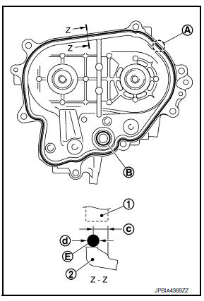
- Apply a continuous bead of liquid gasket (E) using suitable tool to valve timing control cover as shown.
(1) : Front cover
(2) : Valve timing control cover
(A) : Start and end of gasket application
(B) : Liquid gasket application area
(E) : Gasket
(c) : 4.0 - 5.6 mm (0.157 - 0.220 in)
(d) : 3.4 - 4.4 mm (0.134 - 0.173 in)
NOTE:
The start and end of gasket application must overlap 5 mm or more with one another.
Use Genuine Silicone RTV Sealant, or equivalent. Refer to GI-21, "Recommended Chemical Products and Sealants".
CAUTION:
- Installation should be done within 5 minutes after applying liquid gasket.
- Do not fill the engine with oil for at least 30 minutes after the components are installed to allow the sealant to cure.
- Tighten bolts in numerical order as shown.
NOTE:
Tighten bolt the No.1 in two step. The numerical order No.6 shows the second step.
- Install new O-ring to cylinder block
CAUTION:
- Do not misalign O-ring.
- Do not reuse O-ring.
- Apply a continuous bead of liquid gasket (D) using suitable tool to front cover as shown.
(1) : Cylinder head
(2) : Front cover
(A) : Liquid gasket application area
(b) : 4.0 - 5.6 mm (0.157 - 0.220 in)
(c) : 3.4 - 4.4 mm (0.134 - 0.173 in)
Use Genuine Silicone RTV Sealant, or equivalent. Refer to GI-21, "Recommended Chemical Products and Sealants".
CAUTION:
- Installation should be done within 5 minutes after applying liquid gasket.
- Do not fill the engine with oil for at least 30 minutes after the components are installed to allow the sealant to cure.
- Check that matching marks of timing chain and each sprocket are still aligned. Then install front cover.
CAUTION:
- Check O-ring on cylinder block is correctly installed.
- Be careful not to damage front oil seal by interference with front end of crankshaft.
- Install front cover, and tighten bolts in numerical order as shown.
- Refer to the following for the installation position of bolts.
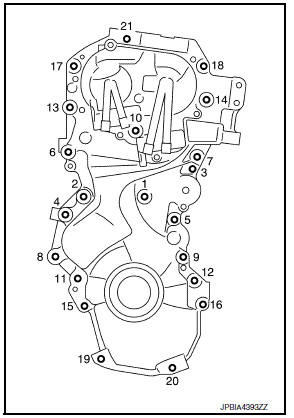
M6 bolt : No. 1
M10 bolts : No. 6, 7, 10, 13, 21
M12 bolts : No. 2, 4, 8, 11
M8 bolts : Except the above
- After all bolts are tightened, retighten them to specified torque in numerical order as shown.
CAUTION:
Be sure to wipe off any excessive liquid gasket.

- Install crankshaft pulley with the following procedure:
- When inserting crankshaft pulley with a plastic hammer, tap on its center portion (not circumference).
CAUTION:
Do not damage front oil seal lip.
- Secure crankshaft pulley (1) using suitable tool (A).
- Apply new engine oil to thread and seat surfaces of crankshaft pulley bolt.
- Tighten crankshaft pulley bolt.
Crankshaft pulley bolt : 29.4 NВ·m (3.0 kg-m, 22 ft-lb)
- Put a paint mark (B) on crankshaft pulley (2), matching with any one of six easy to recognize angle marks (A) on crankshaft pulley bolt (1) flange.
- Turn another 60 degrees clockwise (angle tightening).
- Check the tightening angle with movement of one angle mark.
- Check that crankshaft rotates clockwise smoothly.
- Installation of remaining components is in the reverse order of removal.
Inspection
INSPECTION AFTER REMOVAL
Timing Chain
Check for cracks (A) and any excessive wear (B) at link plates and roller links of timing chain. Replace timing chain if necessary.
INSPECTION AFTER INSTALLATION
- Before starting engine, check oil/fluid levels including engine coolant and engine oil. If less than required quantity, fill to the specified level. Refer to MA-11, "Fluids and Lubricants".
- Use procedure below to check for fuel leakage.
- Turn ignition switch “ON” (with engine stopped). With fuel pressure applied to fuel piping, check for fuel leakage at connection points.
- Start engine. With engine speed increased, check again for fuel leakage at connection points.
- Run engine to check for unusual noise and vibration.
NOTE:
If hydraulic pressure inside chain tensioner drops after removal and installation, slack in guide may generate a pounding noise during and just after the engine start. However, this is normal. Noise will stop after hydraulic pressure rises.
- Warm up engine thoroughly to check there is no leakage of fuel, or any oil/fluids including engine oil and engine coolant.
- Bleed air from lines and hoses of applicable lines, such as in cooling system.
- After cooling down engine, again check oil/fluid levels including engine oil and engine coolant. Refill to the specified level, if necessary.
- Summary of the inspection items:
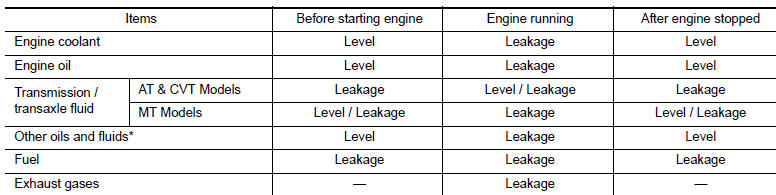
*: Power steering fluid, brake fluid, etc.
 Rocker cover
Exploded View
Oil filler cap
Rocker cover protector
Oil filler tube
O-ring
Rocker cover
Rocker cover gasket
Refer to INSTALLATION
Removal and Installation
REMOVAL
Remo ...
 Camshaft
Exploded View
Camshaft position sensor (EXH)
O-ring
Camshaft bracket
Camshaft (EXH)
Camshaft sprocket (EXH)
Camshaft sprocket (INT)
Camshaft (INT)
Valve lifter (EXH)
Valve lif ...
Other materials:
Push-button ignition switch positions
LOCK (Normal parking position):
The ignition switch can only be locked in this
position.
The ignition switch will be unlocked when it is
pushed to the ACC position while carrying the
Intelligent Key or with the Intelligent Key inserted
in the port.
The ignition switch will lock when any d ...
P0196 EOT Sensor
DTC Logic
DTC DETECTION LOGIC
NOTE:
If DTC P0196 is displayed with DTC P0197 or P0198, first perform the
trouble diagnosis for DTC P0197 or
P0198. Refer to EC-264, "DTC Logic".
DTC No.
CONSULT screen terms
(Trouble diagnosis content)
DTC detecting condition
Possib ...
Wiring diagram
Power door lock system
Wiring diagram
Intelligent key system
Wiring diagram
Trunk lid opener
Wiring diagram
...
