Nissan Sentra Service Manual: System description
COMPONENT PARTS
Component Parts Location
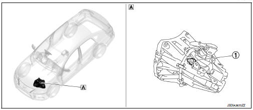
- Transaxle assembly
STRUCTURE AND OPERATION
Sectional View
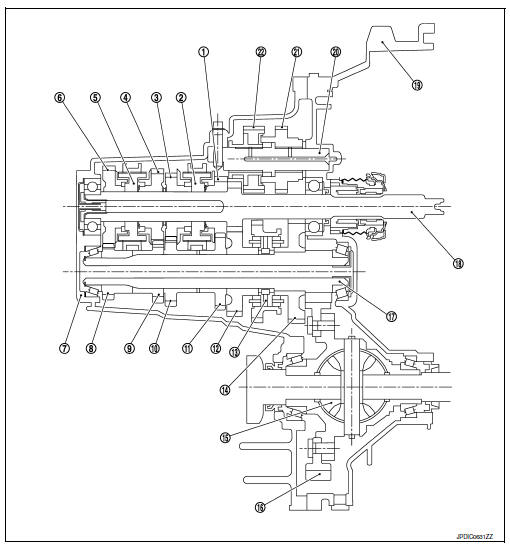
- 3rd input gear
- 3rd-4th synchronizer hub assembly
- 4th input gear
- 5th input gear
- 5th-6th synchronizer hub assembly
- 6th input gear
- Transaxle case
- 6th main gear
- 5th main gear
- 4th main gear
- 3rd main gear
- 2nd main gear
- 1st-2nd synchronizer hub assembly
- 1st main gear
- Differential
- Final gear
- Mainshaft
- Input shaft
- Clutch housing
- Reverse idler shaft
- Reverse input gear
- Reverse output gear
System Description
Triple-cone synchronizer
Triple-cone synchronizers are adopted for the 1st and the 2nd gears to reduce operating force of the shifter lever.
- 1st main gear
- 1st-2nd coupling sleeve
- Insert key
- Outer baulk ring
- 2nd main gear
- Synchronizer cone
- Inner baulk ring
- 1st-2nd synchronizer hub
Reverse gear noise prevention function (synchronizing method)
Reverse gear assembly consists of reverse input gear, return spring, reverse baulk ring, and reverse output gear. When the shifter lever is moved to the reverse position, the construction allows smooth shift operation by stopping the reverse idler shaft rotation by frictional force of synchronizer.
- Reverse fork rod
- Reverse output gear
- Return spring
- Reverse baulk ring
- Reverse input gear
 Preparation
Special Service Tools
The actual shape of the tools may differ from those illustrated here.
Commercial Service Tools
...
 DTC/Circuit diagnosis
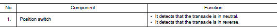
POSITION SWITCH
BACK-UP LAMP SWITCH
BACK-UP LAMP SWITCH : Component Inspection
1.CHECK BACK-UP LAMP SWITCH
Disconnect position switch harness connector. Refer to TM-21, "Removal
and In ...
Other materials:
Removal and installation
Ipdm e/r
Exploded view
Ipdm e/r
IPDM E/R cover A
Ipdm e/r cover b
Removal and installation
Caution:
Ipdm e/r integrated relays are not serviceable and must not be removed
from unit.
Removal
Remove inlet air duct (upper). Refer to em-25, "removal and
installation" ...
Checking engine coolant level
Check the coolant level in the reservoir when
the engine is cold. If the coolant level is below
the MIN level B , add coolant to the MAX level
A . If the reservoir is empty, check the coolant
level in the radiator when the engine is cold. If
there is insufficient coolant in the radiator, fi ...
P060B ECM
DTC Logic
DTC DETECTION LOGIC
DTC No.
CONSULT screen terms
(Trouble diagnosis content)
DTC detecting condition
Possible cause
P060B
CONTROL MODULE
(Internal control module A/
D processing performance)
ECM internal analog/digital conversion processing
syst ...
